ANATOMY OF A BARE-METAL SYNTH, PART 3
This is the third part in a series about a bare metal synth. It assumes knowledge from the the previous post about UART signals and MIDI.
Receiving UART Data on the Daisy
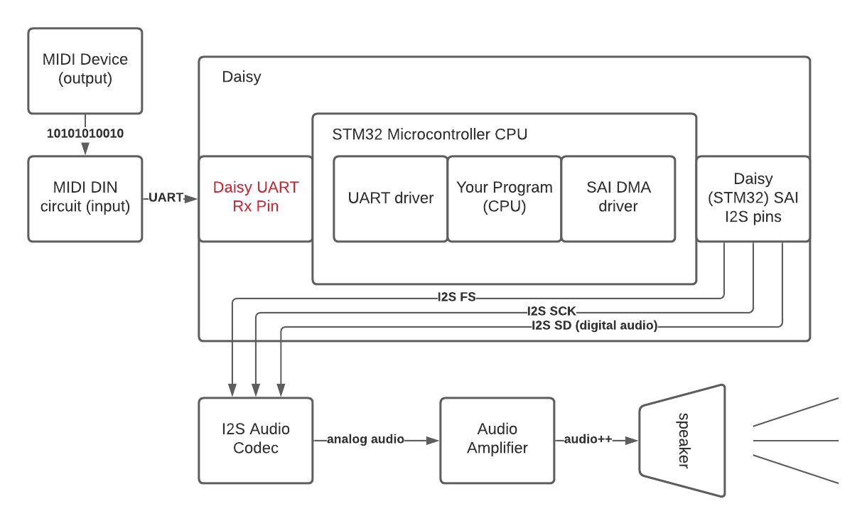
In the last post, we talked about what MIDI is (a UART signal) and the circuit involved with preparing the MIDI signal to be sent to the Daisy. But how do we take the output from that circuit and use it in our code?
The first step is to find where to connect the output to the Daisy. The connections to the outside world on a microcontroller are called “pins”, and we need to find a pin that will accept our UART signal and feed it to the Daisy’s UART driver.
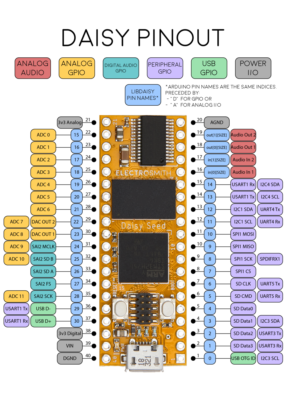
This diagram above is known as a “pinout”. It diagrams all of the available pins on the Daisy and what they can be used for.
NOTE
You’ll see the letters “Rx” and “Tx” a lot in embedded documentation. These stand for “receive” (input) and “transmit” (output), respectively. In our case, we only are interested in receiving MIDI output, so we don’t have to worry about the Tx cases specifically. An example of a case where we would want to transmit MIDI would be a MIDI processor such as an arpeggiator.
Using this diagram, we want to find the UART Rx pin, because our keyboard is transmitting a MIDI signal to be “received” by the Daisy. In this particular pinout, you’ll see the pin we want (pin 15) marked as “USART” (Universal Synchronous/Asynchronous Receiver/Transmitter). In this case, the difference between UART and USART does not matter, because USARTs can handle regular UART signals as well, like the one we are sending.
But you’ll notice – many of the pins, including the USART pin, have more than one function listed. What does that mean? How do we tell the Daisy that we want to send a UART signal to pin 15, rather than an I2C signal which is also listed for pin 15?
Multiplexing
The term for assigning multiple potential uses to a signal pin is “multiplexing” (or sometimes “muxing”). Multiplexing helps to save space. While it might be more straightforward to have a single function exposed on every pin without having to mess around with configuration in the code, not every application is going to need every function from every pin. So multiplexing keeps the space footprint of the board down.
General Purpose Input/Output Pins
The multi-purpose pins themselves are called “General Purpose Input Output” pins, or
GPIOs. These pins can be assigned to any of the labeled functions and internal peripherals
depending on configuration in the software. So we need to find a way to set up the pin
configuration in our code such that pin 15 is in “USART Rx” mode, which makes it ready to
receive our MIDI signal. Luckily, this is handled in libDaisy for us.
Daisy MIDI UART Config
Once we are set up to send UART to the UART pin on the Daisy, the UART/MIDI data goes through a driver so that it can reach our application.
libDaisy implements two wrappers we can look at for the particular case of UART MIDI handling.
The first is the MidiHandler class in midi.h/cpp. This class is how our application
code can interface with the MIDI hardware without worrying about hardware details. It handles both
dealing with the hardware peripherals as well as the parsing that interprets the raw data from
the UART as MIDI messages that our application can use. This class
also contains the second wrapper, UartHandler (uart.h/cpp), which abstracts away the details of
dealing with the STM32 hardware abstraction library (HAL) that sets the registers that interact
directly with the UART peripheral.
Diving into these two files can teach you a lot about how a UART driver is implemented.
The following is how the MidiHandler configures the UART class, notably setting the baud rate to the
one specified by the MIDI spec (31250), initializing the USART_1 peripheral, and telling the
USART_1 peripheral to use GPIO port B pin 7 as the “receive” pin and GPIO port B pin 6
as the “transmit” pin.
UartHandler::Config config;
config.baudrate      = 31250;
config.periph        = UartHandler::Config::Peripheral::USART_1;
config.stopbits      = UartHandler::Config::StopBits::BITS_1;
config.parity        = UartHandler::Config::Parity::NONE;
config.mode          = UartHandler::Config::Mode::TX_RX;
config.wordlength    = UartHandler::Config::WordLength::BITS_8;
config.pin_config.rx = {DSY_GPIOB, 7};
config.pin_config.tx = {DSY_GPIOB, 6};
uart_.Init(config);
But wait, how did we choose those pins? On the pinout earlier, weren’t the USART1 pins 14 and 15? Well, they were indeed, and this is one of the areas where you will be forced to dive into some datasheets to figure out what’s up. The pins exposed by the Daisy translate to pins exposed by the STM32 microcontroller, and the mapping does not use identical numbers.
To find the mapping, you will need to look at the Daisy’s datasheet, which lives here. In there, you’ll find a table called “pin functions”. The leftmost column shows the numbers on the pinout, so if we go to 14 and 15, we will see that these pins map to PB6 and PB7.
This whole thing can be confusing – but in short, you can use the pinout as a guide for which pin to look for in the datasheet, and then use the table in the datasheet to determine which GPIO port and pin you would actually reference in code.

NOTE
GPIO pins are grouped into ports, and Px is a common short hand for “port X”, but you’ll also see it as “GPIOx”, as in this case, where PB6 is shorthand for “GPIO port B, pin 6”.
So now the pins are initialized to be in “receive MIDI” mode. Now that these pins can receive data, how do we access that data from our code?
Polled Approach
The simplest way to read UART data in your programs is to use a “polling” approach. This means that our code, which runs on the CPU, will continuously block and ask the UART register whether it has any data available. If used in a “blocking” mode, our program will be unable to continue until we receive the data we requested.
The Daisy UART library exposes polling functionality in its UART wrapper via this function:
/** Reads the amount of bytes in blocking mode with a 10ms timeout.
\param *buff Buffer  to read to
\param size Buff size
\param timeout How long to timeout for (10ms?)
\return Data received
 */
int PollReceive(uint8_t* buff, size_t size, uint32_t timeout);
The implementation is also very simple. It is a single call into the STM32 HAL which just waits until data is written to the UART register and then writes that data to the buffer that we supplied.
int UartHandler::Impl::PollReceive(uint8_t* buff, size_t size, uint32_t timeout)
{
    return HAL_UART_Receive(&huart_, (uint8_t*)buff, size, timeout);
}
This approach is too inefficient for most applications. Your entire program has to wait until data is available and can’t do any other work in the meantime, which means it is just sitting around waiting most of the time. That’s where the next approach comes in…
Direct Memory Access
To get around this approach of blocking your entire program on the CPU while waiting for data to arrive, a special peripheral exists called a Direct Memory Access (DMA) peripheral. This peripheral allows us to simply place a request for data and then continue on with our program until that data is ready. We supply the data buffer we want filled, the amount of data we want, and a “callback” (function pointer) known as an “interrupt” which will be called once our request has been filled. In the time between making the request and servicing the request when it is ready, our program is free to use the CPU to do any work/calculations it needs.
NOTE
Back there we mentioned a special callback known as an “interrupt”. These are special predefined functions (usually using special names provided by the HAL) that we can provide. These functions will be called by peripherals, interrupting the usual control flow on the CPU, so that we can respond to realtime events. (In this case, the event is “data received”, but it could be any sort of message, such as program aborted, data sent, temperature too cold, etc.)
Learn more about interrupts here.
What does DMA look like on the Daisy?
The MIDI wrapper on the Daisy uses the DMA functionality of the UART wrapper rather than
the polling method. The UART wrapper exposes a function called StartRx. This function
invokes HAL_UART_Receive_DMA, which in turn intitates a DMA request on our UART peripheral.
The request includes a FIFO buffer that holds UART data until the MIDI wrapper is ready to use it.
HAL_UART_Receive_DMA(
        &huart_, (uint8_t*)dma_fifo_rx_->GetMutableBuffer(), rx_size_);
Once DMA has been initiated, the calling code can continue doing whatever else it needed
to do (set up other peripherals, calculate DSP coefficients, etc). When data has been
sent to our UART, a special interrupt will be called, HAL_UART_RxCpltCallback. In this callback,
the pointers in the FIFO are advanced (since the DMA has written data to that FIFO now). This
signals to the outside world that MIDI data is available.
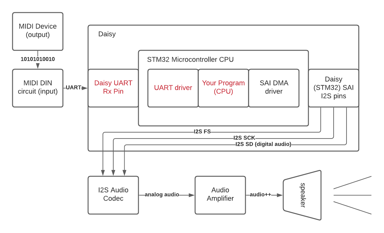
Putting it into context
We have covered a number of important concepts in embedded development: GPIOs, multiplexing, interrupts, and DMA. Don’t feel discouraged if some or all of these went over your head; the best way to understand these concepts is to tinker around with examples in Daisy (or whichever platform you are dealing with). My hope is that you can come back to this article while diving into the libDaisy and STM32 HAL source code to get some context for what is going on.
Before moving on, here is an example provided by the Daisy folks that shows how the actual application code calls the MIDI handler. I’ve added some comments to tie back to the concepts we have discussed:
int main(void)
{
    // Init
    float samplerate;
    hw.Init();
    samplerate = hw.AudioSampleRate();

    // This portion multiplexes our USART1 GPIOs to receive UART MIDI MIDI
    midi.Init(MidiHandler::INPUT_MODE_UART1, MidiHandler::OUTPUT_MODE_NONE);

    // This call on the MIDI handler initiates the DMA requests to start
    // filling up the internal UART MIDI buffer
    midi.StartReceive();
    hw.StartAdc();
    hw.StartAudio(AudioCallback);

    for(;;)
    {
        // Now we loop while listening for MIDI data.
        // This line sees if we have any data available in the
        // UART buffer that was handled by DMA, parses the raw UART
        // bytes as MIDI, and adds a new MIDI event to the queue
        midi.Listen();

        // if we received MIDI data on the line above,
        // then pop off midi events from the queue until our
        // application has handled all available data.
        while (midi.HasEvents())
        {
            // This is where our magic happens --
            // we use the MIDI event to generate audio
            // in response
            HandleMidiMessage(midi.PopEvent());
        }
    }
}
Next up: Application Code
In the next article, we will dive deeper into the above code and show the specific handling that we use to respond to MIDI messages to create audio. See you there!