ANATOMY OF A BARE-METAL SYNTH, PART 2
This is the second part in a series about a bare metal synth. For an introduction to this series, see the previous post.
MIDI Circuitry
The first section of our synth circuit deals with MIDI input. MIDI will be routed from some external source – could be a keyboard MIDI controller, a sequencer, or a series of hardwired buttons.
In our case, we will use the old school 5 pin MIDI connector, because it is simpler to understand and hook up compared to something like USB MIDI.
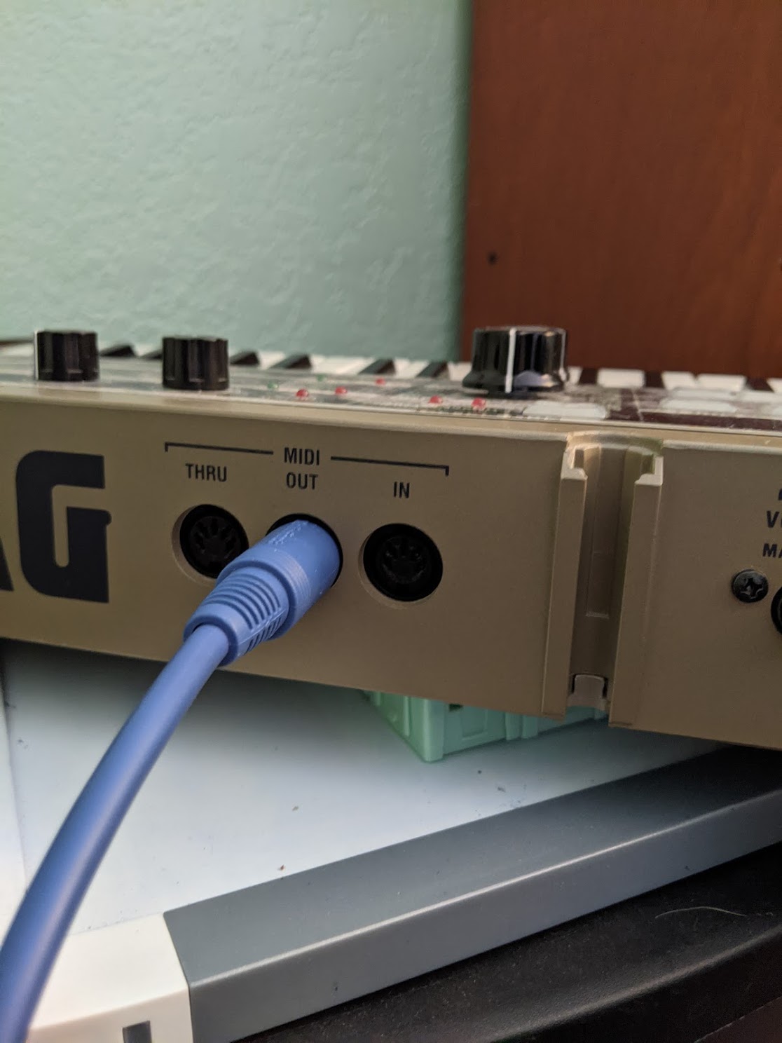
We can hook up the 5 pin MIDI din to our breadboard using something like this Sparkfun female MIDI jack.
But before we go into the MIDI circuit itself, let’s answer a more fundamental question…
What is MIDI?
MIDI is a special kind of signal known as a “serial communication protocol”. These types of signals are very important to understand in all forms of embedded programming – they are the way that peripherals on an embedded device communicate with one another. Types of protocols include UART, SPI, I2C, and I2S.
At their core, serial communication protocols are electrical impulses of binary data (square waves) that hold no intrinsic meaning unless both sides of the communication understand and agree what language they are speaking. For instance, if a microcontroller has a SPI interface and we try to hook that up to an I2C peripheral, the signal will have no meaning and the communication will fail.
Embedded systems are really a web of peripherals talking to one another using these protocols, and writing small drivers for them can be a great way to learn. For example, a small project with a microcontroller hooked up to an I2C temperature sensor that can print out temperature values at a regular rate over UART can be a good intro project to get started.
I2C
For a visual example, here is the Phillips spec for the I2C protocol. I2C has two signals connecting
the peripherals – a data line and a clock line.
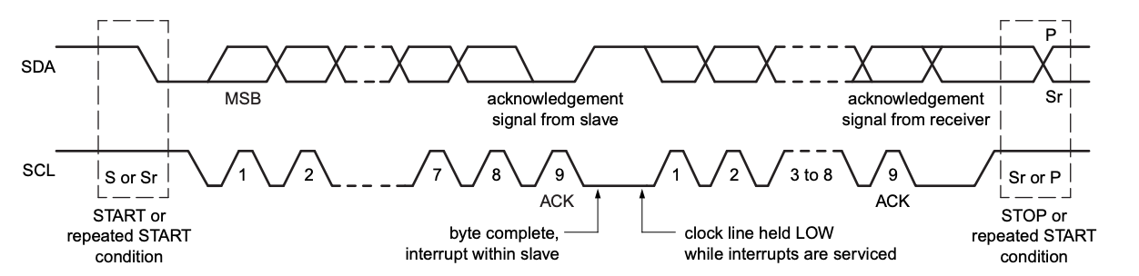
The top line – the “data” line – is a square wave that has actual data (temperature, motor control, new sample rate setting for an audio interface, etc). The bottom signal – the clock line – is a syncing mechanism so the receiving side knows where each byte of the data line starts and stops and offers an integrity check for the data line. The use of a clock line defines I2C as a “synchronous” protocol.
UART
A simpler mechanism for communciation involves only one signal: UART, the universal asynchronous transmitter/receiver.
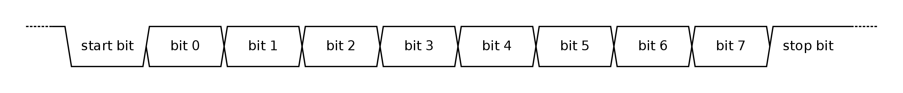
Unlike synchronous protocols like I2C which require a clock line, asynchronous protocols use the rate of data transfer (the “baud rate”, in bits-per-second, bps) to determine the length of each bit, acting like an “implicit” clock. Both sides of the UART, transmitter and receiver, must be set to the same baud rate, otherwise the data will be misinterpreted.
UART is most commonly used as a mechanism for transmitting characters, which is how you can hook up a remote “terminal” to a bare metal device for sending commands and receiving text output back. However, UART can also send other types of data packets, which brings us back to MIDI at last…
MIDI can be transmitted over UART
Our 5 pin MIDI DIN connector is really a special type of UART that sends and receives MIDI packets.
There are other ways (transport mechanisms) to transmit MIDI such as USB and Bluetooth, which have advantages over the MIDI DIN approach, but are more complicated. And as long as retro synths are
popular, 5 pin MIDI will still have a use in music tech.
The official MIDI spec defines 5 pin MIDI DIN as a series of data packets sent over a single UART line at a baud rate of 31250. For an in-depth introduction to MIDI, see this Sparkfun article.
Now let’s get back to the circuit!
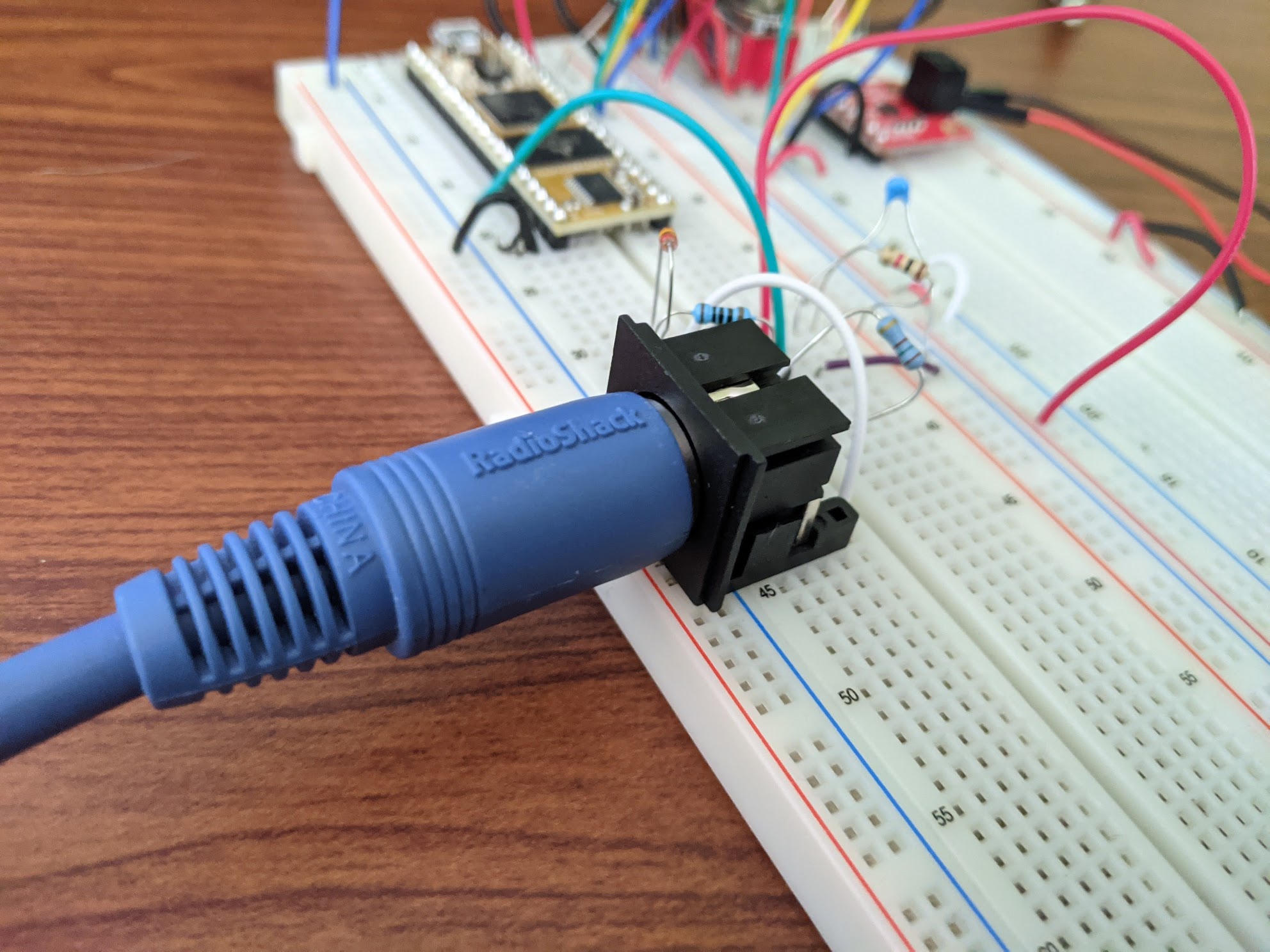
MIDI in Context
Here is the Daisy synth on a breadboard again, this time with the MIDI circuit circled in red.
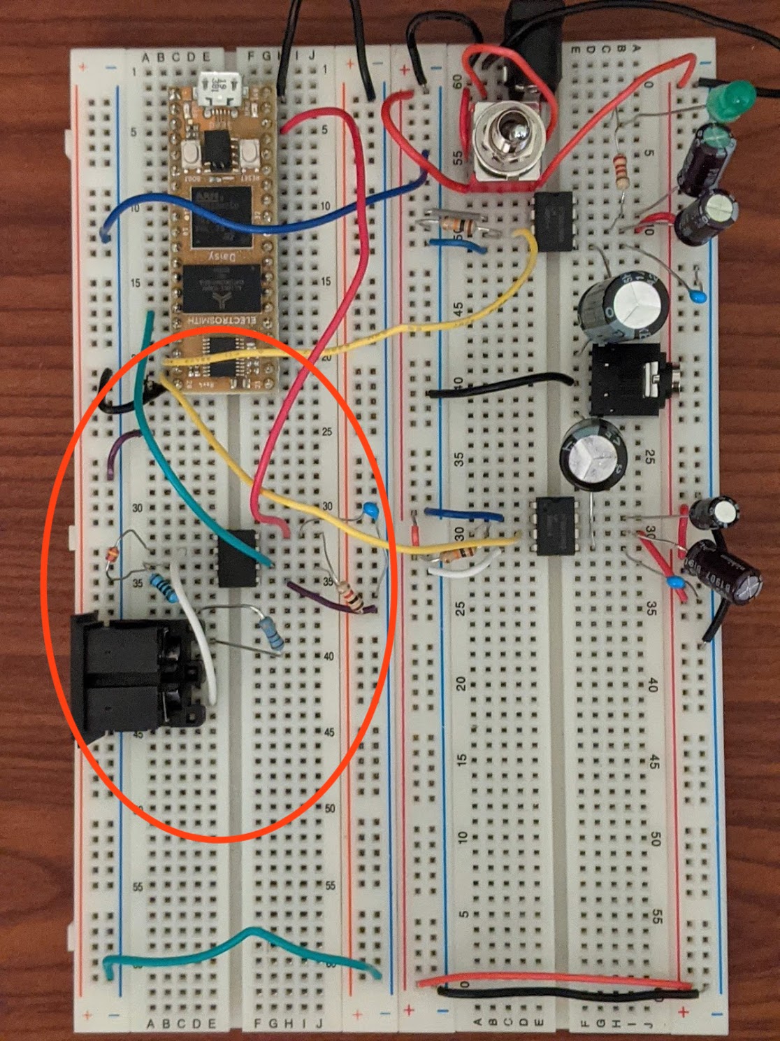
We said before that MIDI is just a single UART line – why isn’t it just one wire that we connect right into the Daisy? What is all the other stuff in that circle?
MIDI Optoisolator Circuit
It turns out the MIDI spec dictates not only the MIDI data itself, but also the
circuitry used to connect MIDI devices together. Technically, you physically could connect one MIDI
device to another directly, but this would be a bad idea, because this direct electrical
connection between two black boxes with different power supplies can create noise known
as a ground loop. Ground loops
are especially heinous in audio applications which we want to be free of buzzes and hums!
The spec’d MIDI input circuit gets around this problem by electrically isolating the MIDI output device from our circuit, while still being able to communicate MIDI from that device.
Here is a schematic of that circuit from Notes and Volts:
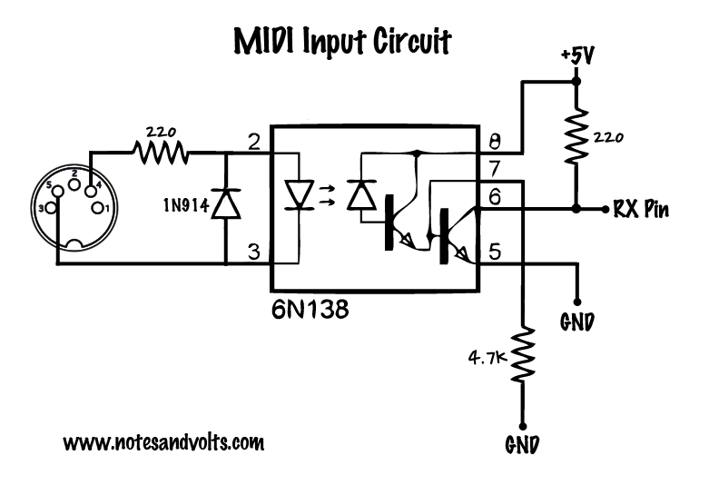
The most interesting part of this circuit is the little arrows in the middle. This is the key component of the “optoisolator” IC, in this case the 6N138. (A 6N137 can do the trick as well, and is what I’m using in the breadboard pictures)
This component processes the signal from the Korg like so:
- Takes an electrical output signal from another device (MIDI)
- Converts that signal into a series of light blinks from an LED
- The photodiode (or sometimes a phototransistor) sitting next to the LED converts that signal back to electrical current
- The IC outputs the signal coming from the transistor
In other words, the IC converts the MIDI from an electrical signal to light and back to an electrical signal in order to avoid a direct electrical connection between the two MIDI devices. A neat solution!
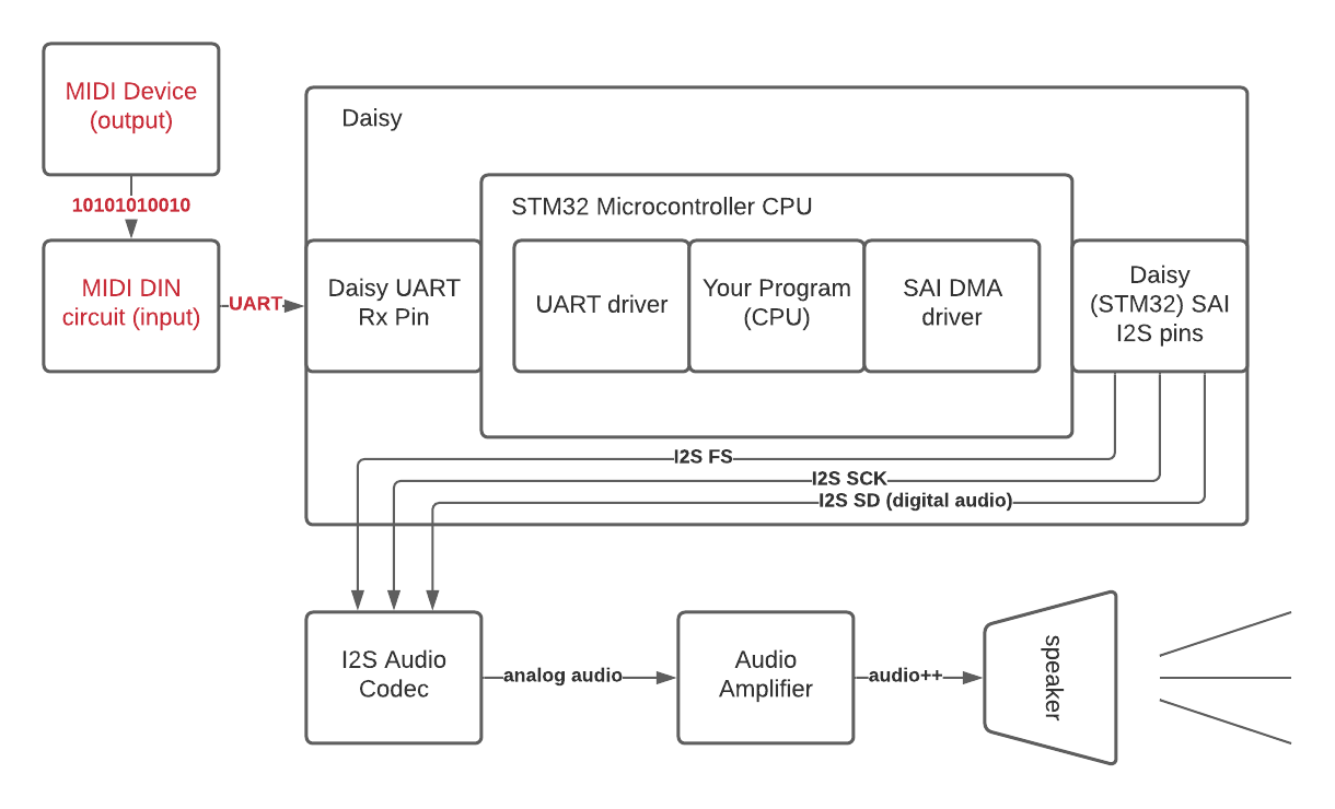
Next up: UART Driver
To cap it off, we can see in the breadboard picture that the teal wire coming out of the little black
optoisolator IC is what goes into the Daisy. (The red wire is +5V (powering the chip) and the black one is connected to ground) The Daisy pin which that teal wire is connected to is the UART Rx (receive) pin, which hooks up to the UART driver. More info on that coming up next!