ANATOMY OF A BARE-METAL SYNTH, PART 6
This is the final part in a series about a bare metal synth. See the previous post for info needed here.
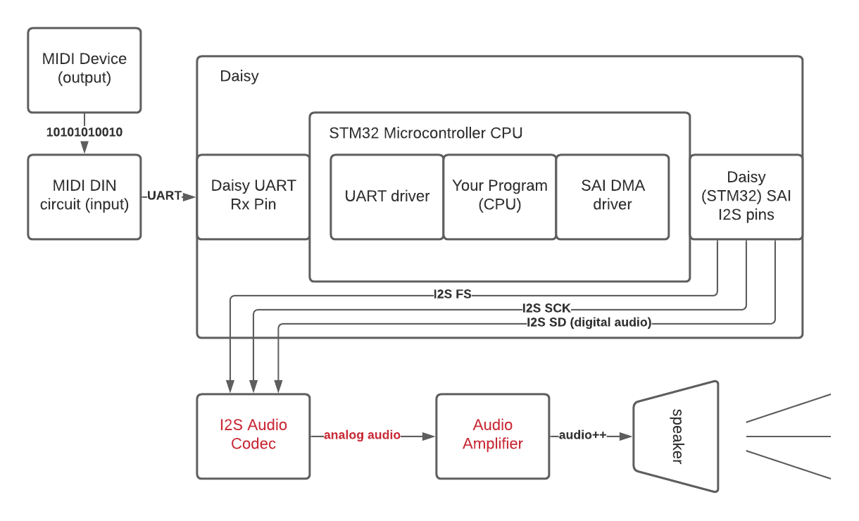
We last discussed how audio makes it from our program to the serial audio interface. Next up is the following portion of the flow diagram, where the SAI exposes that audio as I2S data available on a series of pins we can hook up to.
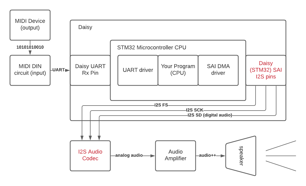
Note that Daisy abstracts some of this by default, by sending the SAI I2S signal to the on-board AK4556 audio codec, which then exposes the analog line-level audio output on pins 18 and 19 that we can hook up directly to a speaker. This means we don’t strictly need to hook anything up manually to the I2S pins exposed by the SAI if we are ok with the conversion done by the AK4556, since those connections are also made internally for us for convenience.
But I think it is useful to briefly dig into this abstraction a bit by exploring what it would be like to hook up our own codec; just note that this next section isn’t strictly necessary to implement in your application, and we use the provided audio outputs in our actual synth as well to save breadboard real estate.
Appendix: Digital Audio Exposed on GPIOs
One option for supplying your own external audio codec fed by Daisy’s I2S pins is to get a breadboardable I2S breakout board. These boards are convenient for prototyping and usually include an onboard audio amplifier so that the output is a ready-to-go amplified analog audio signal.
Here is what our circuit looks like if we hook up to one of these boards:
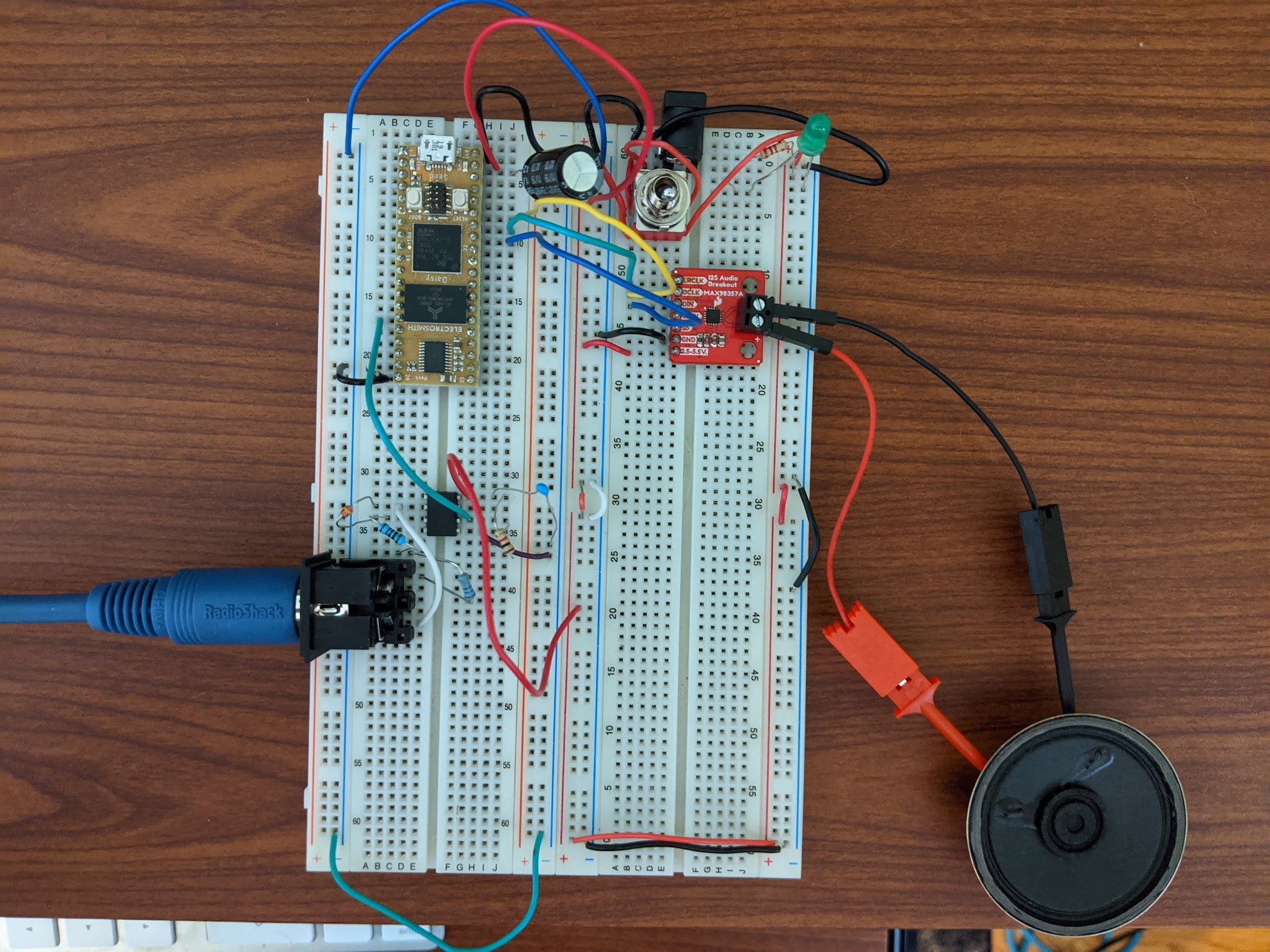
These accept input from the pins that we multiplexed above, all of the I2S lines:
frame synchronization: whether the current bit being read is the left or right channelbit clock: synchronization so we can tell which where the bytes of the other data lines begin and enddata line: the digital audio data on the current channel
sai_config.pin_config.fs = {DSY_GPIOE, 4}; // frame synchronization
sai_config.pin_config.sck = {DSY_GPIOE, 5}; // bit clock
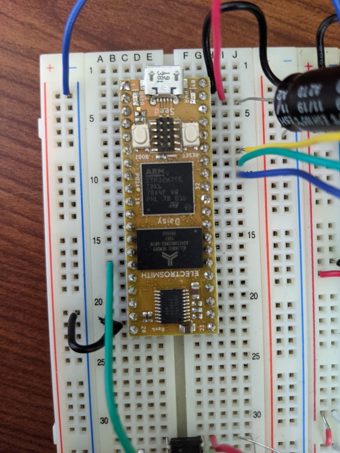
sai_config.pin_config.sa = {DSY_GPIOE, 6}; // data lineThose three pins come out of the Daisy here, pins 35, 34, and 33 (from top to bottom):
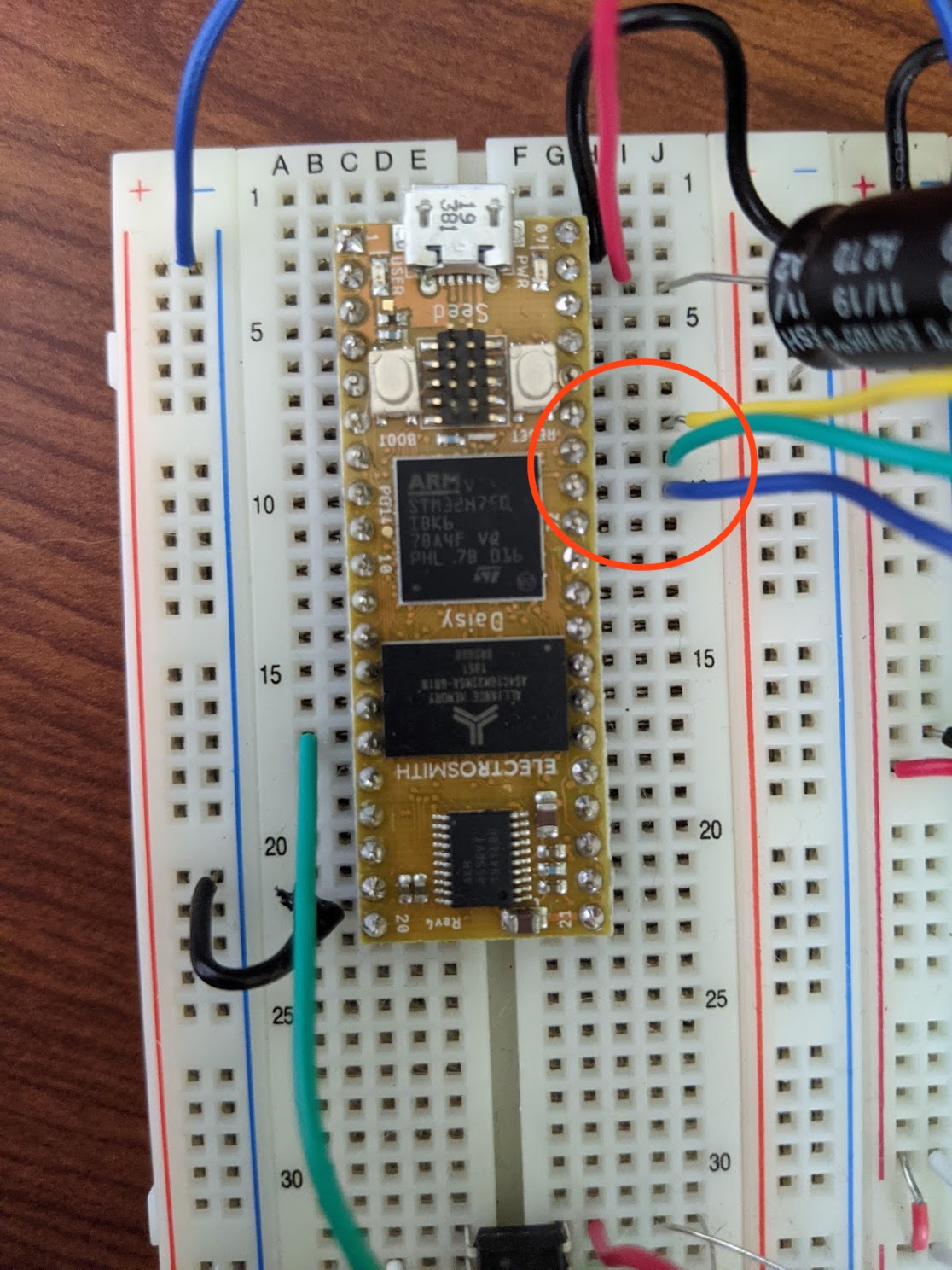
And we connect those three lines into the breakout board like so (see the Sparkfun link for more info on their input/output pins):
- SAI1 FS (“frame synchronization”) -> LRCLK (“left right clock”)
- SAI1 SCK (“serial clock”) -> BCLK (“bit clock”)
- SAI1 SA (“serial A”) -> DIN (“data in”)
- Ground line
- Power line
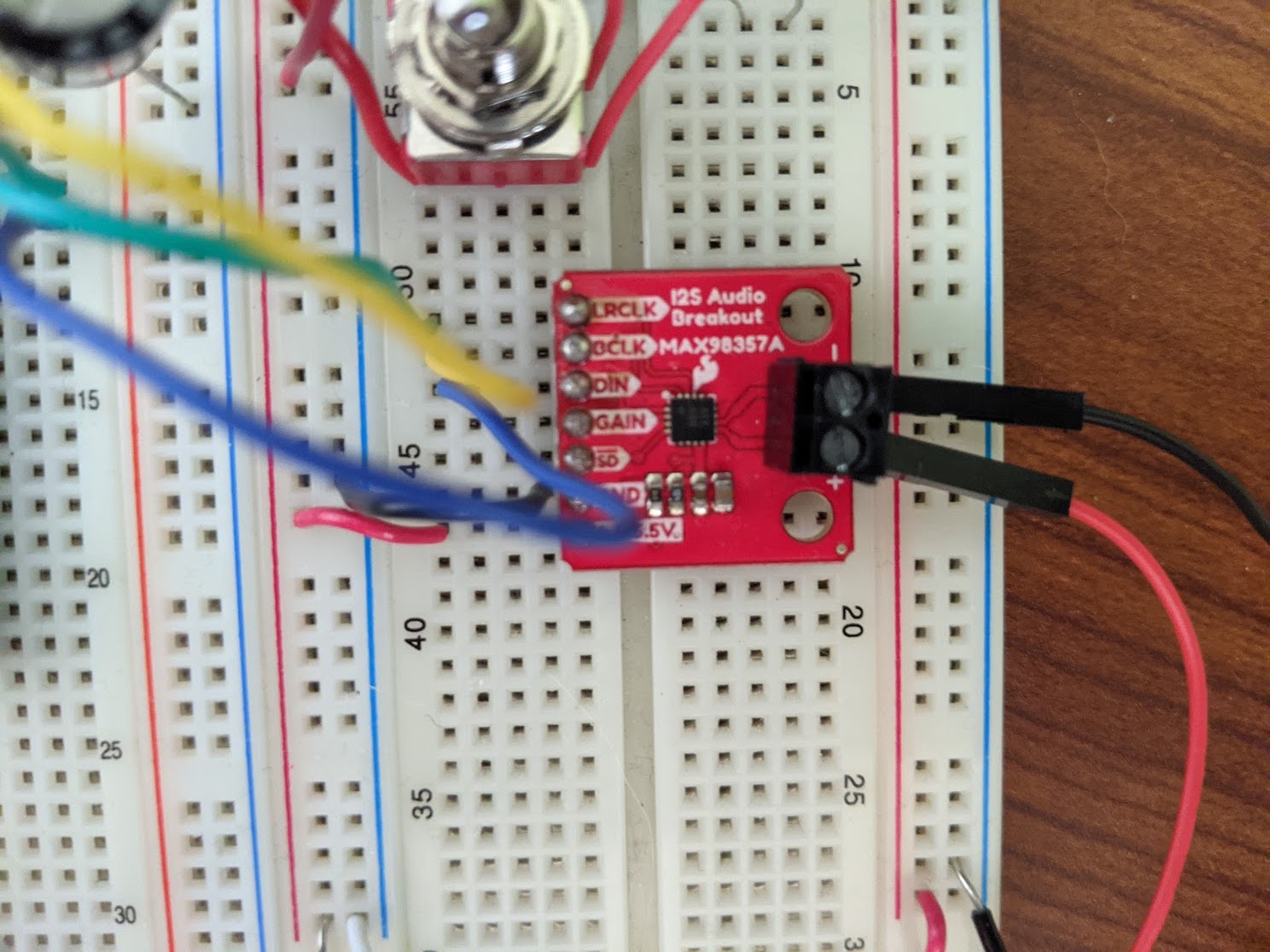
The breakout board then sends the output of the DAC to an amplifier (whose gain can be controlled by other pins exposed as inputs) and the resulting analog audio output can be hooked up to headphones or a speaker.
Appendix: Amplifying Analog Audio
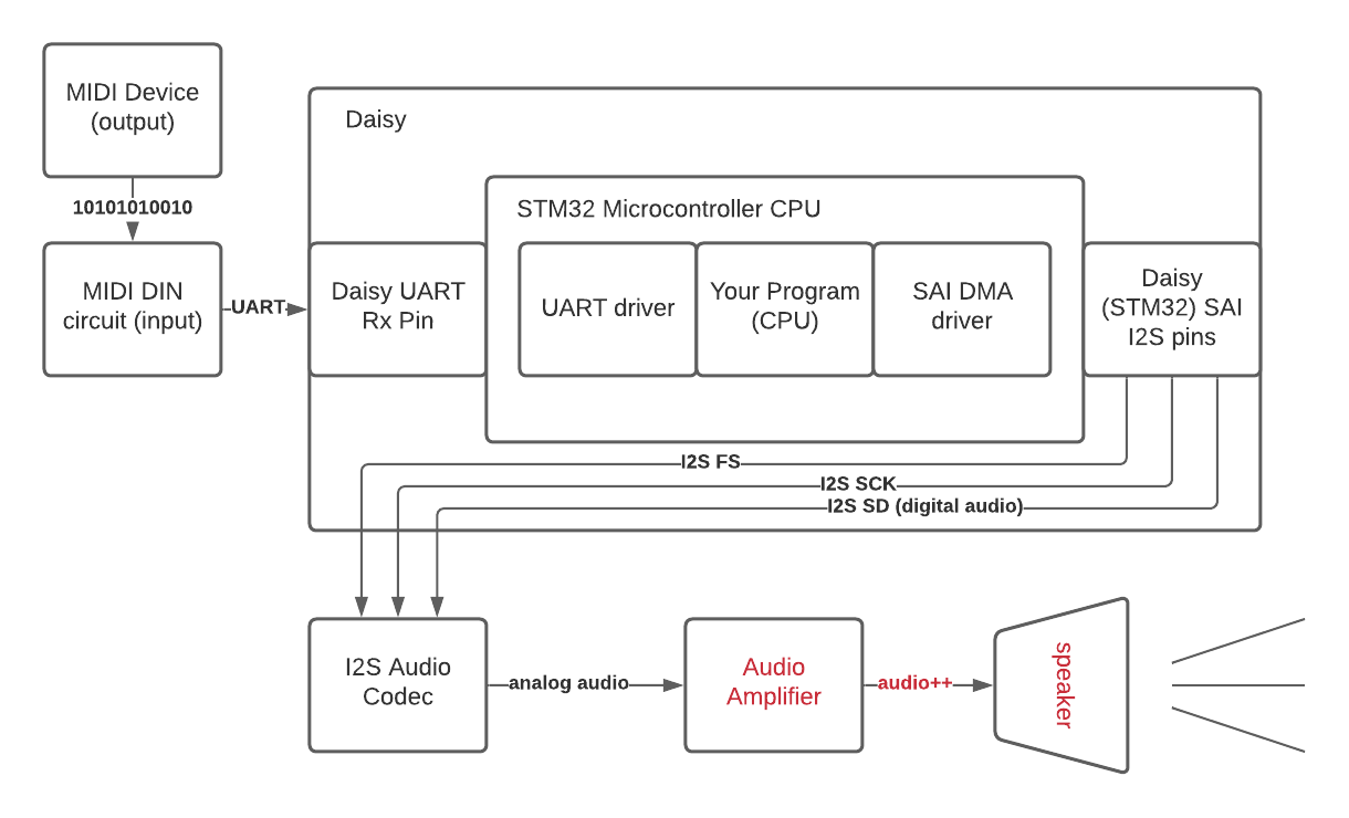
Another important piece of our flow diagram that is abstracted away (this time by the breakout board) is the audio amplification stage:
When we use the breakout board from the last section, this part is included without our intervention. However, the audio we receive from the DAC on the Daisy is line-level, so if we plug headphones or unpowered speakers directly into it, it will be much too quiet to hear at a usable level.
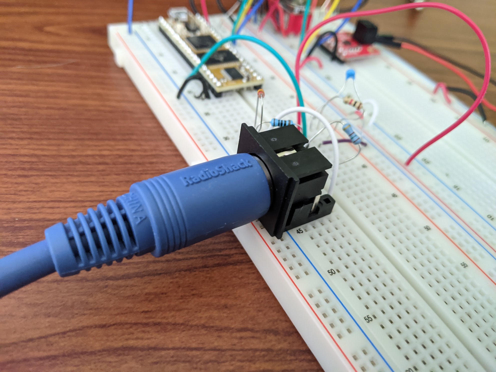
In contrast to the last section, here is what our synth looks like if we use the default configuration of the Daisy and hook up to the analog outputs from the AK4556 codec.
We also added a pair of headphone amplifiers for the left and right output signals to boost the line level audio coming out of the AK4556 so that we can hook up unpowered speakers or headphones directly to this output.
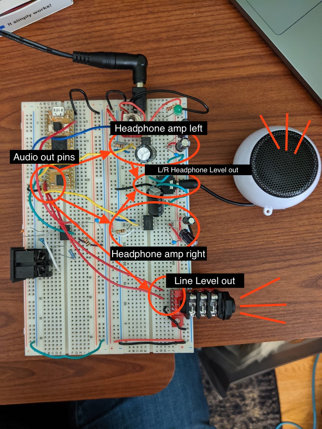
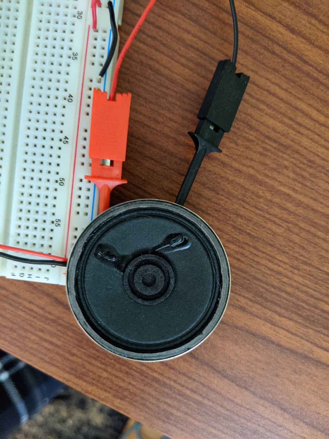
The connection to the speaker in the above also marks the final part in the flow diagram: analog audio to amplifier to speaker!
The headphone amps on the breakout board are based on the LM386 audio amplifier chip. We set up the surrounding components (resistors/capacitors), pipe audio into it, and we get louder audio out! The design is taken from this helpful article which explains the circuit in more depth:
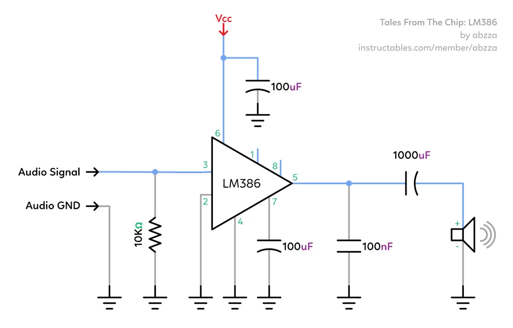
And here is one of the amplifiers on its own, breadboarded out based on that schematic:
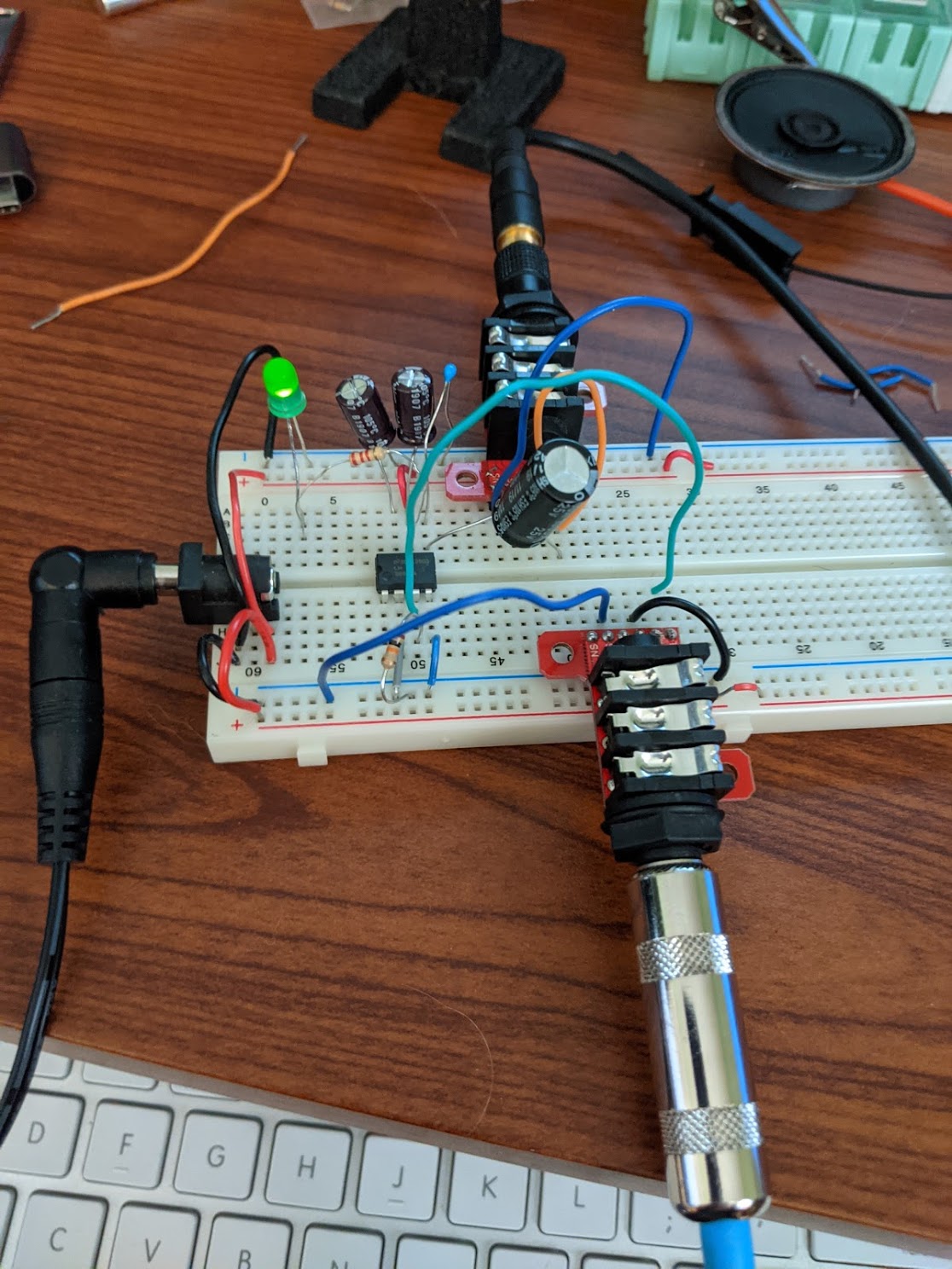
NOTE You’ll see in all my breadboard photos that there is a wall wart power circuit before the “actual” circuit begins. This is a really helpful way both to supply power to your breadboard circuits without needing to buy a ton of 9V batteries and to debug that power is actually making it to your circuit. You can build it with:
- A universal AC adapter; I got a Belker for about $13
- A breadboard-able DC jack
- Through-hole DPDT switch
- LED and small resistor
If you set up the circuit like so, then you will have power and ground buses on the breadboard available to the rest of your circuit, you can use the switch to turn the power on or off (much better than crouching down to plug it every time!) and you can use the LED to know if the power is truly off and whether you can safely mess with the components.
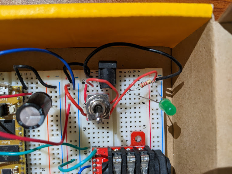
I’d recommend breadboarding this part of the circuit first before anything else, and just making sure that the LED goes on and off and that your power/ground rails on the breadboard are working as expected. This will greatly help your troubleshooting loop once you get into making the actual circuit.
Wrapping Up
And that’s pretty much it! Now that we have gone through everything with this little synth, I’d like to recap just a bit to go over all the points in the system now that we have gone into more detail over the course of these articles.
To recap – the signal first comes out of our MIDI controller or some other source.
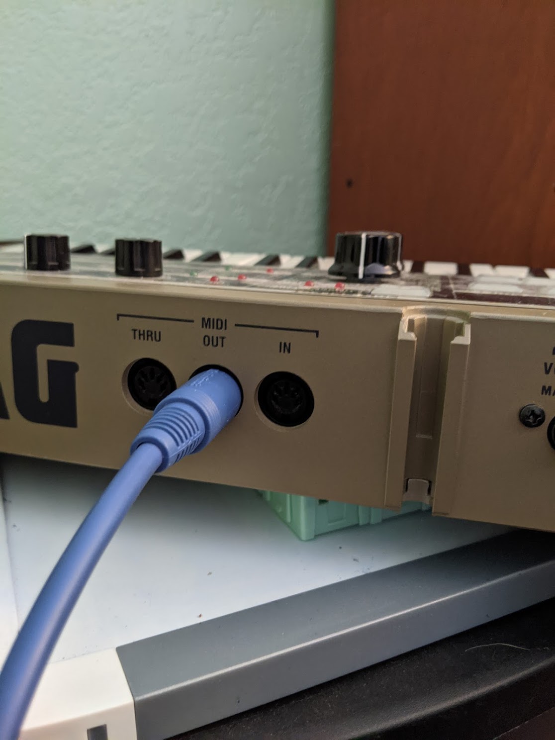
The MIDI at this point is just a signal UART line, and we need to electrically isolate that UART signal from the other MIDI source using our MIDI input circuit.
From that circuit, we will get the isolated MIDI UART signal on this green wire going into the Daisy on the left. From here, all our magic happens with:
- The UART going into the STM32 UART driver
- The DMA interrupt telling our MIDI library that MIDI is available
- Our program plumbing that MIDI into our VoiceHandler
- The VoiceHandler generating audio
- The SAI sending that audio to the I2S lines
- The audio coming out as digital I2S audio on the three wires on the right side of the Daisy
Those three digital audio lines going into a digital-to-analog converter breakout board (which also amplifies the audio):
The amplified audio signal being sent to a speaker.
Thanks so much for reading and feel free to reach out with any questions. I hope this article series inspires you to try and build some stuff, and I’d love to hear about it! :)