DEVELOPING AUDIO PROGRAMS FOR EMBEDDED LINUX, PART 2
In my first embedded Linux post, we covered how to write a dead-simple ALSA program and cross compile it for an ARM embedded device. Next, we need to figure out how to configure I2S audio to come out on pins from the Beaglebone, hook those pins up to our external DAC and audio amplifier, deploy our cross compiled ALSA program to our Beaglebone, and run the thing!
In this article we will discuss communication protocols (I2S, I2C, SPI, UART), Linux device trees, and ALSA configuration, which are all deep topics on their own. In many instances I’m going to link to more in-depth articles, so hopefully this post can act as a jumping board for you to get more deep on this stuff. Let’s start!
Materials
- Beaglebone Black
- I2S DAC and audio amplifier. This one from Sparkfun is cheap and works great!
- Speaker (I got a 4” 8ohm speaker)
- Jumper wires and breadboard
- Host computer (mine was on Debian Stretch but it can work with others)
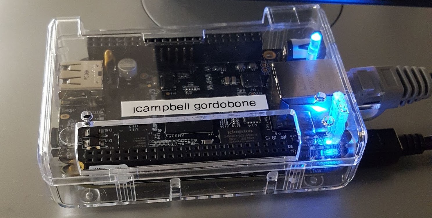
Set up the Beaglebone Black
Before anything, let’s quickly make sure your Beaglebone Black is functional. For simplicity, this article assumes that
you are using the Beaglebone-supplied Linux image on your board, but the concepts still apply if you made your own image
using Buildroot as described in the last article. A fair amount
of the discussion is Beaglebone/AM335x specific, but intended to be presented in a way that you could investigate a different
embedded Linux board you might be working with such as a Raspberry Pi.
The official docs on how to set up the Beaglebone should get you to
a place where you can run the code in this article. Make sure you can ssh into your board after following those
instructions by invoking this command on your host, to which the Beaglebone is USB connected:
ssh debian@beaglebone.local # default password is temppwdAlso, as stated in the Beaglebone docs, always make sure you power down the board before unplugging it! Otherwise you may end up needing to start the bring up process all over.
What’s in a circuit?
Before deep diving into anything, here is a high level overview of our circuit and data flow we want to accomplish by the end of
this article:
- Run our ALSA program (
booper) on the Beaglebone - This program connects to the default audio device, which is
plughw:Black,0(you can find the available audio devices usingaplay -L) - We read audio output from this device using the McASP enabled pins, which output the audio as an I2S data stream (this data is also being sent to the HDMI output, but we don’t use that)
- We connect these pins and power to the corresponding inputs of the I2S Digitial-to-Analog Converter (DAC) breakout board
- The breakout board also includes an amplifier to bring the analog audio output to a reasonable amplitude before running it into the speaker
Or put another way, we are going to ask our Beaglebone to direct the audio from our application to a particular audio device, which we will configure to output the audio as I2S, so that it can talk to our breakout board that speakers I2S. Before getting into any of that configuration: what is I2S?
Communications Protocols are Key
One thing I’ve found from learning embedded systems is that communication protocols are a central topic for figuring out how to build things.
After all, an embedded system is really just a hodgepodge of isolated (usually specialized) components talking to one another – so how
do they do it? They send electrical data signals to one another and agree on what they are supposed to mean!
Different communication protocols have different tradeoffs – some require a bunch of wires and clock signals and might be more reliable or faster than others but require a ton of pin real estate, while others might only require a single wire but have lower throughput. Understanding and considering these tradeoffs is a key skill, so I would recommend getting familiar with all the major communication protocols. The big ones are UART, I2C, SPI, USB and the one focused on in this article, I2S. I2S has persevered for a long time as an audio protocol because it is simple and its tradeoffs are specially designed to work with high bandwidth (44.1kHz) stereo audio signals.
What is I2S?
A solid and simple overview of I2S can be found here. I chose it for this project because it is an industry standard for digital audio transmission between ICs and is well suited to the high data rates in a stereo audio signal. Another common way to get audio out of the Beaglebone is over USB using a USB DAC, but eventually I wanted to add USB MIDI support to a small program and I’d rather still have the USB port open. So I2S it was!
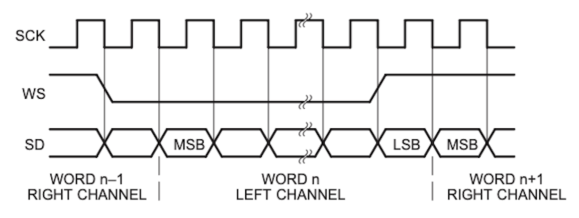
That figure was taken from the official Phillips I2S spec.
I would recommend reading the spec – it’s just a few pages because it’s very simple as far as specs go! USB for example is way hairier… getting comfortable with reading technical specs is a key skill in embedded software development.
The protocol is made up of:
- Continuous Serial Clock (SCK): This is the clock signal that keeps all the bits in sync according to the desired sample rate.
- Word Select (WS, sometimes LRCLK): Since the audio line can contain data for the left or right channels, this clock describes which channel is currently being transmitted (low means left channel and high is right)
- Serial data (SD): This pin will have the actual audio data for the left and right channels.
I2S docs and this article use the nomenclature “left and right channels”, but in practice you can implement higher channel counts like 5.1 and 7.1 by adding additional I2S buses.
One drawback of the I2S audio output on the Beaglebone is that the on-board clock only supports the 48kHz family of sample rates (so if you want 44.1kHz or multiples of that, you’ll need to set up your own external clock). See here for more details on why that is. The I2S outputs are pretty easy to get at, because they are also used for the HDMI output, which has a handy writeup here.
How do I get I2S audio out of my Beaglebone?
Now that we know what I2S audio is, we have to figure out how to access the I2S audio output of the Beaglebone. Full disclosure: since HDMI output is enabled by default on the Beaglebone, the I2S pins are actually already enabled on a factory configured Beaglebone! But I wanted to dig into where that configuration lives and how you could conceivably apply this investigation to any embedded Linux board, or if you are setting up a BBB image from scratch using Yocto or Buildroot.
Manuevering an info search…
When I was initially looking around for info on how audio works on the Beaglebone, I found that it helped to directly look at resources about the Beaglebone’s processor, the Sitara AM335x. The Beaglebone has a fair number of resources, but especially if you are working with a less common platform, you may have a very hard time limiting yourself to the platform-specific docs. I was tempted for awhile to gloss over the processor itself, but using it in my Google searches for technical specs and help articles turned out to be really important. Technical specs tend to be very dry and hard to understand for beginners, but you won’t be able to run away from them forever – so I recommend embracing them early on to answer your questions that come up!
In this case, all I knew is that I had an I2S breakout board and wanted to get I2S audio output from the pins on the Beaglebone. So the archaeology began…
Knowing the Beaglebone’s processor, I started by just Googling AM335x audio interface! This led me to the AM335x reference manual – searching “audio interface” in this article led me to the section
on TI’s Multi Channel Audio Serial Port (McASP), which is the audio peripheral used on the Beaglebone’s SoC. This gives a good overview about which pins correspond to which parts of the I2S signal that we described above. We now know when we need
to do further research that AM335x, I2S, and McASP are important search terms to use in other documents such as the
Beaglebone’s system reference manual.
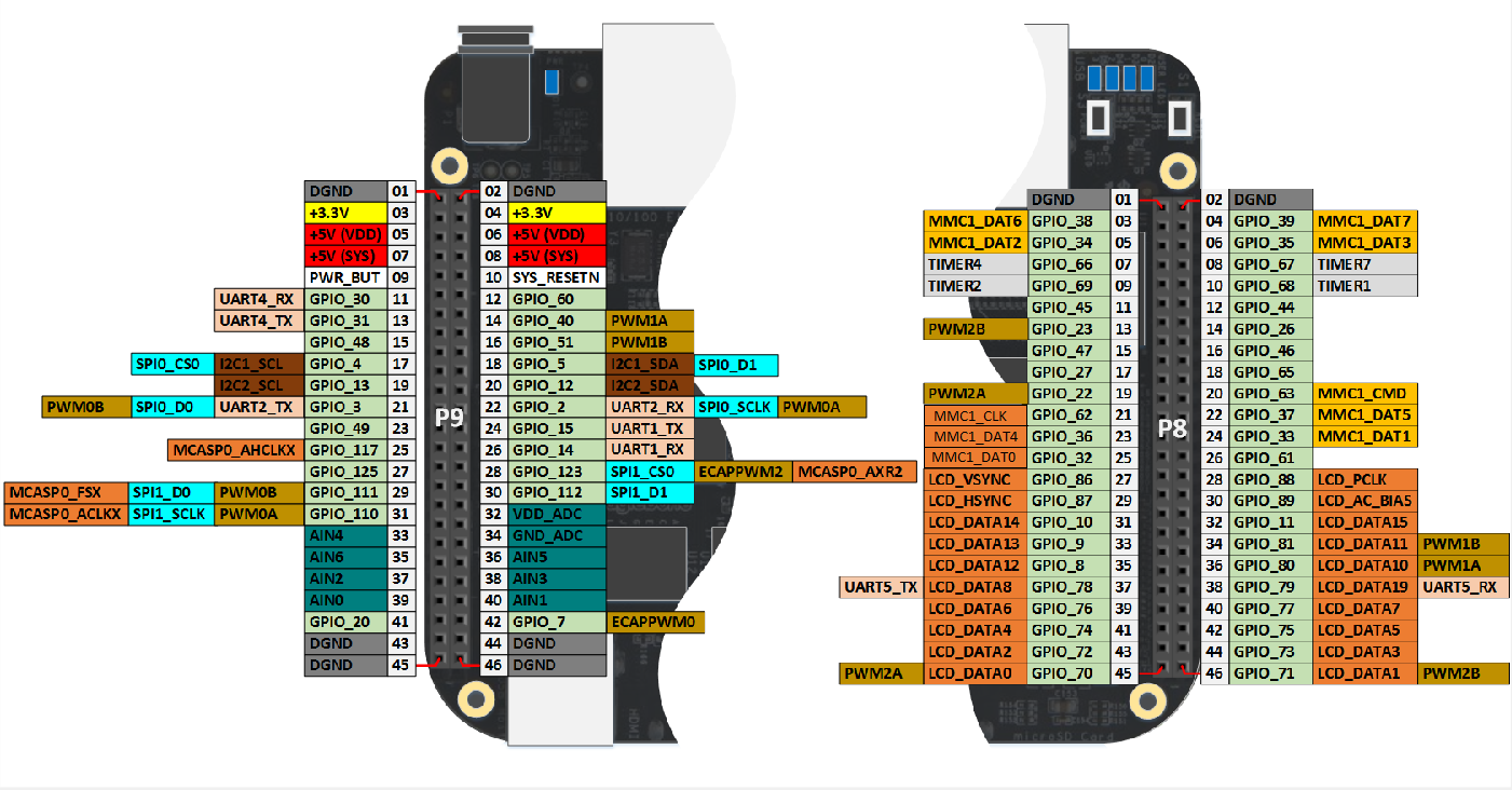
I soon found via this resource which pins could be set to output I2S. However, those pins can do more than just output I2S (they can be GPIOs, SPI, or PWM as well).
Here is a quick table for which pins (all on the P9 header) we will need to connect to our I2S breakout:
BBB Description	    Header pin      	Description
MCASP0_AXR2         P9_28           	Bitstream (audio data)
MCASP0_FSX          P9_29           	Left/Right clock
MCASP0_AHCLKX       P9_31           	Bit clock
GND                 P9_01               Ground
VC3V3               P9_03               Power
So how do we get audio out of them?
Pin Multiplexing
For a general purpose dev board like a Beaglebone, there are a ton of different ways one might want to use the pins and fairly
limited physical space. To solve this problem, embedded SoCs will allow for the same pin to be connected in different ways
via configuration in software via a technique called “pin multiplexing”, or “muxing”. The same exact physical pin can be set to
connect to the audio interface and output a bit clock or instead be configured as a GPIO. On the Beaglebone Black, there are
almost 69 I/O pins on the device but the rest of them can also be used for other predefined functions.
For context, if size wasn’t an issue, we wouldn’t need pin multiplexing – we could just have a pin for every signal we wanted to be able to input or output from the board.
So we need a way to mux the pins identified in the previous section so that they are connected to the McASP interface and output I2S signals. In a bare metal scenario, one would simply write to the pin directly in their application, set it to output mode, and tell it to be an I2S pin. Things are a little more complicated in embedded Linux land however; from user space (as opposed to kernel space), the modern way to multiplex pins on Linux is via the device tree.
Linux Device Tree
The Linux device tree became popularized over the last decade as a way to get unneeded hardware specifics out of the Linux
kernel and instead describe available hardware peripherals in a modular file known as a “device tree blob” loaded by the kernel
at runtime. The source for a device tree looks a lot like C source code, and has
borrowed features from C such as include files. Device trees are loaded in a hierarchical fashion, such that a core device
tree file is defined and parts of it can be overridden by other files known as “device tree overlays”. The device tree is
a pretty complex topic and I recommend reading other articles about it that explain more in depth, like the Raspberry Pi’s
article on them. There are also great articles
at Of Itself So about the device tree overall on the BBB and using the device tree to configure pinmux. Device tree source files have a .dts extension, so you can learn a lot by
greping for this on your board to see what’s available, or in the Linux kernel to see what device tree overlays are available
upstream.
Two good audio-specific device tree overlays that you should digest are the BBB AudioCape and the Bela device tree overlay.
You shouldn’t need to edit device tree overlays yourself in many use cases, at least on platforms like BBB and
Raspberry Pi – these platforms have a ton of community device tree overlays written and available, and have external parameters
exposed (dtparams) that are available in board-specific configuration files read at boot time for configuring the device tree
overlays, such as uEnv.txt on BBB and config.txt on the Raspberry Pi.
Configuring audio with the device tree
What we are mainly concerned about in this article is how we use the device tree to enable the McASP audio interface and
mux the associated pins to be in I2S mode.
Before dissecting actual DT code, let’s lay out exactly what we need to accomplish:
- Reserve the McASP pins so that other device tree overlays don’t try to snag them for another purpose (you can run into conflicts here)
- Multiplex those pins to be set to their relevant McASP function
- Enable and configure the McASP device itself
- Add a “sound card” node so we can access the McASP device via ALSA
Again, I want to note that for this case, you won’t need to write this stuff yourself; in most cases it will work out of the box, and when it’s not working, your first action should be to double-check the user defined parameters in the uEnv.txt or config.txt (depending on your board). But understanding what’s going on in the dts files will likely come in handy at some point, especially if you want to design your own cape/hat/daughterboard. And even then you probably shouldn’t be writing one from scratch, but rather using and modifying an existing dts file.
See here for a more in-depth look at the nuts and bolts of DTS syntax.
One challenge you may run into with reading snippets of dts files is determining which keywords are determined by the
device tree spec (such as compatible) and which are just vendor-defined names of nodes defined higher up in the
overlay definition for a specific board like mcasp0. If you don’t know a symbol, don’t be afraid to go looking for
where it is defined. One place to delve is the docs for the sound subdir of the TI Linux kernel fork.
Now let’s dissect a DT overlay used in the BBB audio cape.
Reserve the hardware
As explained in this Adafruit article, the exclusive-use property of a DT node is used to restrict other device tree overlays
from trying to use the specified sets of resources. In this case, we are saying that we want exclusive control over
the I2S pins and mcasp0.
/* state the resources this cape uses */
exclusive-use =
    /* the pin header uses */
    "P9.31",	/* mcasp0: mcasp0_aclkx */
    "P9.29",	/* mcasp0: mcasp0_fsx */
    "P9.28",	/* mcasp0: mcasp0_axr2 */
    "P9.25",	/* mcasp0: mcasp0_ahclkx */
    /* the hardware ip uses */
    "mcasp0";
Mux the Pins
This part is where we use the pinctrl subsystem device tree bindings to mux the mcasp0 pins.
Check out Derek Molloy’s tutorial on BBB DT and GPIOs for some helpful charts he made for the various modes available on all the Beaglebone’s P8 and P9 pins. There you can confirm that mcasp0_ahclkx is indeed MODE0 of P9.25, etc. You can also see in that chart that the GND and power pins only have one mode, so they don’t need to be multiplexed.
You should check out the other McASP pins in the reference manual for setting up external clocks, the high frequency vs regular bit clock, and other variants on the pinmux you might want to do.
fragment@0 {
    target = <&am33xx_pinmux>;
    __overlay__ {

        /* The AudioCape also reserves I2C pins because
           they want to use the onboard AIC31 codec, which
           is controlled by I2C.
           Not all DT overlays will do this. */
        i2c2_pins: pinmux_i2c2_pins {
            pinctrl-single,pins = <
                0x150 0x72 	/*spi0_scl.i2c2_sda,SLEWCTRL_SLOW | INPUT_PULLUP |MODE2*/
                0x154 0x72	/*spi0_d0.i2c2_scl,SLEWCTRL_SLOW | INPUT_PULLUP | MODE2*/
            >;
        };

        /* This is where the McASP pins are muxed. Expect
           to see many variations on this for various capes
           with different needs. */
        bone_audio_cape_audio_pins: pinmux_bone_audio_cape_audio_pins {
            pinctrl-single,pins = <
                0x1ac 0x00      /* mcasp0_ahclkx,       P9_25 | MODE0 | OUTPUT_PULLDOWN (high frequency bit clock) */
                0x19c 0x22      /* mcasp0_axr2,         P9_28 | MODE2 | INPUT_PULLDOWN (audio input) */
                0x194 0x20      /* mcasp0_fsx,          P9_29 | MODE0 | INPUT_PULLDOWN (left right sync clock) */
                0x190 0x20      /* mcasp0_ahclk,        P9_31 | MODE0 | INPUT_PULLDOWN (bit clock) */
                0x198 0x20      /* mcasp0_axr0,         P9_30 | MODE0 | OUTPUT_PULLDOWN (audio output) */
            >;
        };
    };
};
Enable Audio Codec
One aspect of the BBB audio driver we haven’t gone over in depth is the built-in audio codec AIC31 (analog interface chip 31), which is controlled over I2C. In the DT, we just need to make sure that its
I2C controller is enabled. Here is an architecture diagram to show how the AIC3 and McASP port interact.
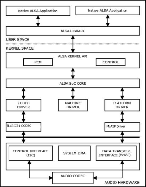
I’m not sure whether setting up the TI audio codec is actually needed if you are using an external codec (I suspect not?) but I’m including this section to describe why this particular DT overlay for the audio cape is configuring I2C pins and the tlv320aic3x in the first place.
Here is TI’s description via their wiki:
(Copied here directly because that wiki is apparently going down in January!)
The AIC31 audio module contains audio analog inputs and outputs. It is connected to the main AM335x processor through the TDM/I2S interface (audio interface) and used to transmit and receive audio data. The AIC31 audio codec is connected via Multi-Channel Audio Serial Port (McASP) interface, a communication peripheral, to the main processor. McASP provides a full-duplex direct serial interface between the host device (AM335x processor) and other audio devices in the system such as the AIC31 codec. It provides a direct interface to industry standard codecs, analog interface chips (AICs) and
other serially connected A/D and D/A devices. The AIC31 audio module is controlled by internal registers that can be accessed by the high speed I2C control interface.
fragment@1 {
    target = <&i2c2>;
    __overlay__ {
        #address-cells = <1>;
        #size-cells = <0>;

        tlv320aic3x: tlv320aic3x@1b {
            compatible = "ti,tlv320aic3x";
            reg = <0x1b>;
            status = "okay";
        };
    };
};
I also want to mention that there is an alternative (newer) syntax for writing DT fragments you may see, which is equivalent to the above but less compatible with some older parsers. Useful to be familiar with it so you know it’s just another fragment.
/* This is equivalent to the fragment
   shown above */
&i2c2 {
    #address-cells = <1>;
    #size-cells = <0>;

    tlv320aic3x: tlv320aic3x@1b {
        compatible = "ti,tlv320aic3x";
        reg = <0x1b>;
        status = "okay";
    };
};
Enable McASP
Now it’s time to enable the McASP audio controller. See the TI docs for more info on what the vendor-specific fields mean.
fragment@2 {
    target = <&mcasp0>;
    __overlay__ {
        pinctrl-names = "default";
        pinctrl-0 = <&bone_audio_cape_audio_pins>;

        status = "okay";

        op-mode = <0>;          /* MCASP_IIS_MODE */
        tdm-slots = <2>;
        num-serializer = <16>;
        serial-dir = <  /* 0: INACTIVE, 1: TX, 2: RX */
            1 0 2 0
            0 0 0 0
            0 0 0 0
            0 0 0 0
        >;
        tx-num-evt = <1>;
        rx-num-evt = <1>;
    };
};
Configure a Sound Card
Now we need to configure a soundcard so ALSA is able to use the audio hardware we set up above. TI has some info about these bindings here.
In this case, we are configuring sound for an ocp (“On-Chip Peripheral”) node.
/* Note the number after the fragment. In a DT overlay,
  make sure these fragments are laid out in order or
  some may be missed by the parser. */
fragment@3 {
    target = <&ocp>;
    __overlay__ {
        sound {
            compatible = "ti,da830-evm-audio";
            ti,model = "DA830 EVM";
            ti,audio-codec = <&tlv320aic3x>; /* Connecting the codec from above */
            ti,mcasp-controller = <&mcasp0>; /* Connecting the McASP defined above */
            ti,codec-clock-rate = <12000000>;
            ti,audio-routing =
                "Line Out",             "LLOUT",
                "Line Out",             "RLOUT",
        };
    };
};
How To Enable Device Tree Overlay
As stated earlier, you probably won’t need to be editing those files directly most of the time. The way that most users interact with the device tree is by “exporting” (activating) various device tree overlays at runtime. Derek Molloy has a great tutorial on how to do this, as does Adafruit.
You also may not need to export device tree overlays this way manually – on the Beaglebone and Raspberry Pi, you choose which device tree overlays to export and which device tree parameters to set using either the uEnv.txt or config.txt, depending on which platform you are using.
Next up: Configure ALSA
The last software step to consider (yet another part where things could go wrong) is in the ALSA configuration.
Now that you have the audio hardware all set up via the device tree and the sound card is available to ALSA,
we need to configure ALSA to actually use that sound card. It’s worth reading ALSA’s doc about asoundrc,
which is a file used to configure ALSA. Sometimes you can expect things to “just work” without configuring ALSA,
so I suggest trying that first – but when things go wrong, you can trying installing a configuration file
like so to /etc/asound.conf.
pcm.!default {
    type hw
    card 0
    device 0
}

ctl.!default {
    type hw
    card 0
    device 0
}
When you load up the board, you can run aplay -l and aplay -L to list the available audio devices to see if
whatwe configured from the device tree is available as expected.
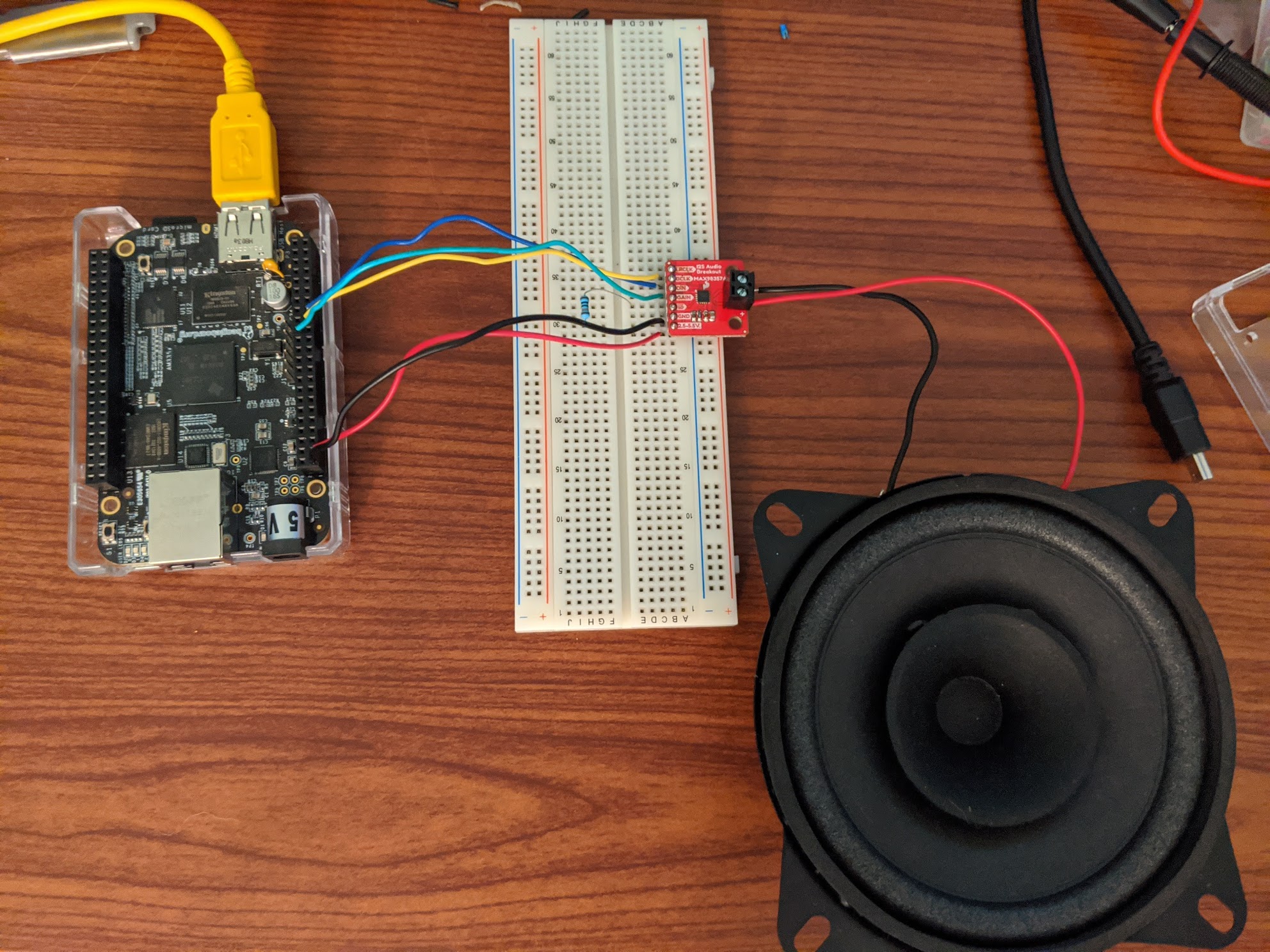
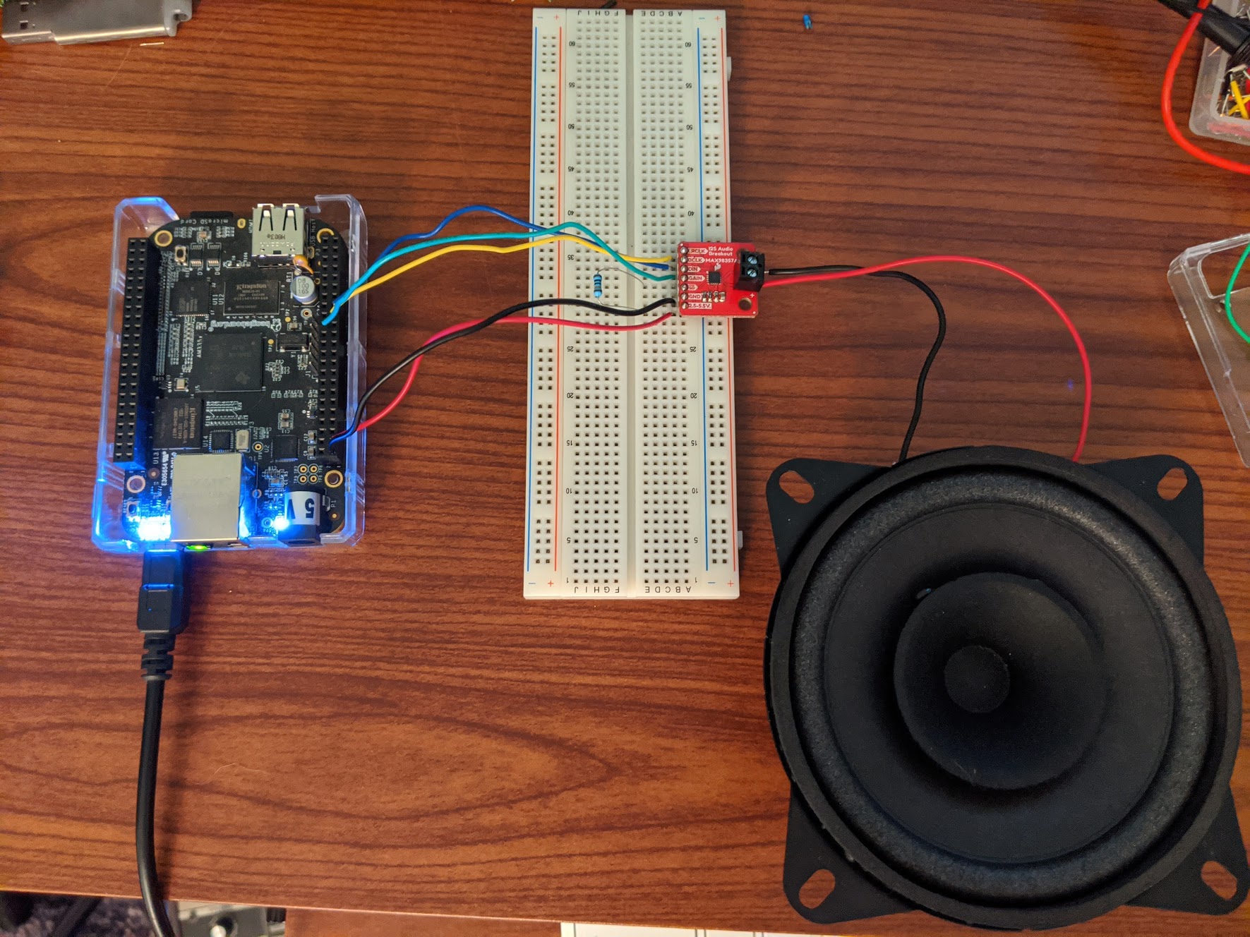
Hooking up the Components
Once the software is finally set up, hooking up the I2S audio breakout is the easy part. I used the MAX98357A from Sparkfun for which they have a handy hookup guide.
First, we need to connect the Beaglebone pins we muxed to the inputs of the breakout board.
One issue I had is that the audio output and input from the BBB seemed to be switched around based on what was documented in the device tree overlay I was using. So even though P9_30 is supposed to be the output, I was actually seeing audio output from P9_28, the supposed audio input! This is a case where having a logic analyzer is handy, because you can visualize what is coming out of each pin. Your mileage may vary, so if P9_28 doesn’t work, try P9_30 for audio output.
BBB pin     MAX98357A Pin    Description
P9_28       DIN              Serial (audio) data BBB output to breakout input.
P9_29       LRCLK            Frame clock (left/right clock).
P9_31       BCLK             Bit clock.
P9_01       GND              Connect to ground
P9_03       VDD              Power from BBB to breakout (3.3V).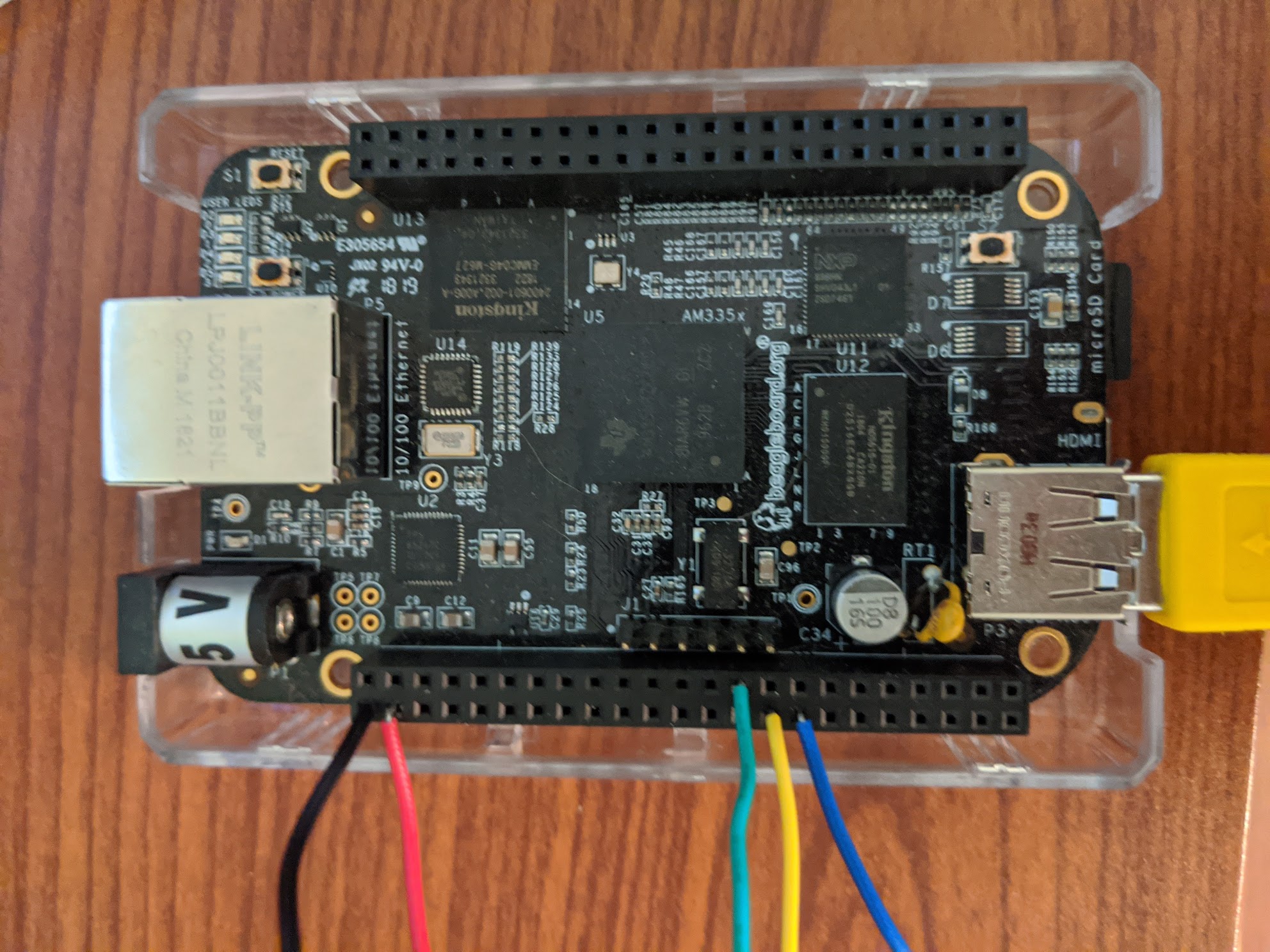
I also used a resistor to VDD to set the gain of the breakout board per their docs, but this is optional.
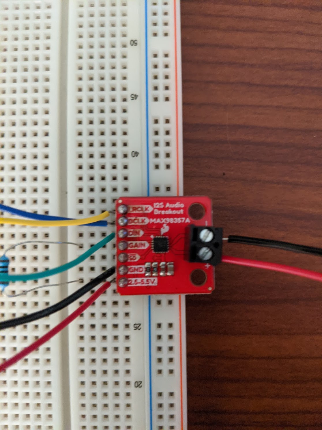
This breakout board is responsible for reading the I2S data stream, converting it to an analog audio signal, amplifying that signal, and sending that amplified signal to a speaker. So the output of this board is a +/- connection to a speaker. Analog audio is susceptible to noise, so the shorter these wires, the better. (The ones I have pictured are pretty long…)
From here, you can do a quick test with the built-in program on Linux, speaker-test -t sine.
Make a sound!
The very last part is to install our ALSA program onto the board and run it!
You can deploy the program from your host to the BBB by navigating to the output directory and running:
scp booper debian@beaglebone.local:./Now go to you Beaglebone’s home directory. You may need to set executable permissions on the file with
chmod x ./booper. After that, run it with ./booper – it should make some noise!
Thanks for reading through all of this! My hope is that this article can serve as a jumping board into many of the deep topics mentioned. Feel free to reach out with any questions, feedback, corrections, or anything!