ANATOMY OF A BARE-METAL SYNTH, PART 5
This is the fifth part in a series about a bare metal synth. See the previous post and more for info needed here.
We will be covering this portion of the flow diagram:
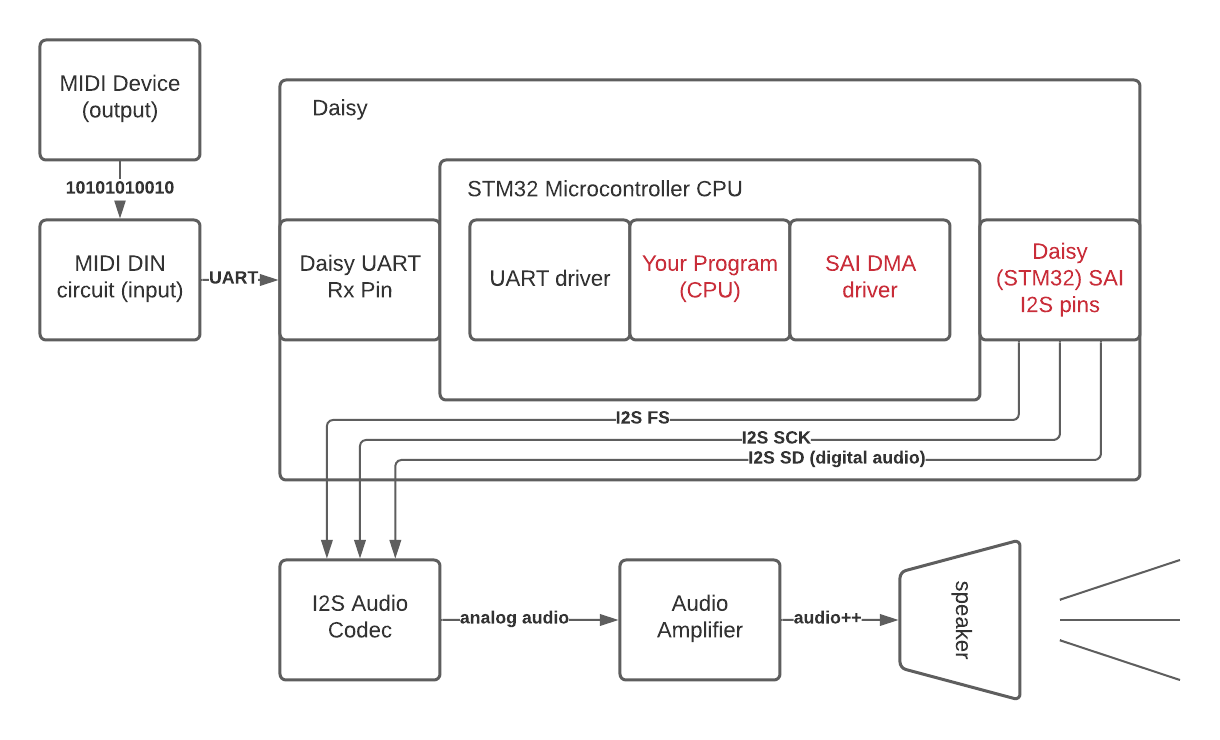
The audio samples (int32_ts) that we generated in our AudioCallback part of our application running on the MCU – where do they go?
The integers themselves represent (gasp for air): discrete values that a digital to analog converter in our system will convert to analog voltages that are output as electrical current to utilize ~electromagentic induction~ to wiggle a connected speaker in such a way that surrounding air particles are disturbed like dominos until those particle oscillations get to the air in our ears and we experience it as sound. (exhale)
SIDE-NOTE: Here are some articles about digital to analog conversion that explain better than my run-on sentence above. Also many cool books and diagrams out there that get into more detail about sampling theory. All this stuff applies to more than just audio; buttons and switches for instance also often use ADCs to convert analog signals to digital ones that a program can react to.
Sparkfun Digital to Analog Conversion
JOS Stanford Introduction to Sampling
But in short, we need a way to get those discrete audio values to the digital-to-analog converter (DAC). This is where the Serial Audio Interface (SAI) comes in.
Serial Audio Interface
The serial audio interface in an embedded system is the way by which software and hardware from elsewhere in the system can request or send audio samples to pins connected to the audio ADC or DAC, respectively.
NOTE: Here is a good doc for more info on how the SAI is structured on the STM32.
In our case, we don’t care about requesting audio samples for input; we want to send audio samples we generated in our application on the CPU to the audio hardware. As mentioned in the last article, we do this by registering a callback (AudioCallback) that the SAI can call when it receives a signal from the DAC that it is ready to convert more samples.
But before we dive further into the mechanics of the communication, we should talk about the format of the audio itself. Digital audio can be transmitted using many different serial communications protocols – in this case, we will configure the SAI to output our audio data in I2S protocol, but it can also be configured for PCM, TDM, SPIDIF, AC’ 97, and others.
Inter-IC Sound (I2S)
Inter-IC Sound (developed by Phillips) is a serial communication protocol just like the ones we discussed before such as I2C and UART, but some of its properties such as reliable clocking, word select, and simplicity make it ideal for dealing with multichannel, high rate audio signals.
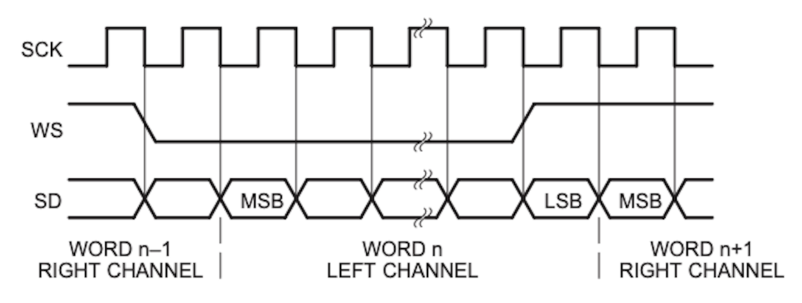
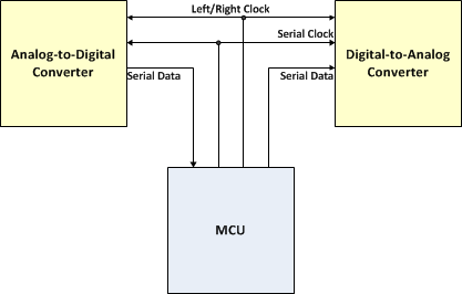
The protocol is made up of:
- Continuous Serial Clock (SCK): This is the clock signal that keeps all the bits in sync according to the desired sample rate.
- Word Select (WS, sometimes LRCLK): Since the audio line can contain data for the left or right channels, this clock describes which channel is currently being transmitted (low means left channel and high is right)
- Serial data (SD): This pin will have the actual audio data for the left and right channels.
I2S docs and this article use the nomenclature “left and right channels”, but in practice you can implement higher channel counts like 5.1 and 7.1 by adding additional I2S buses.
With that background, let’s take a look at how the Daisy configures the STM32 SAI to take our audio samples and output them as an I2S signal.
Daisy Audio Handler Structure
There are several layers that the Daisy library uses to send our audio to the SAI.
- At the topmost level, we have a handle to the “DaisySeed” object
- The DaisySeed has an
AudioHandleobject - In turn,
AudioHandlehas a handle toSaiHandle - Finally, the
SaiHandletalks to theSAI_HandleTypeDefprovided by the STM32 HAL library; this is one layer above talking to registers on the hardware
How Daisy Configures the SAI
We interact with these layers by simply calling the Init function on the Daisy seed:
seed.Init();This bubbles down to the SaiHandle, which is initialized first by configuring the SAI_1 peripheral (there are two SAIs available on the STM32):
SaiHandle::Config sai_config;
sai_config.periph          = SaiHandle::Config::Peripheral::SAI_1;
sai_config.sr              = SaiHandle::Config::SampleRate::SAI_48KHZ;
sai_config.bit_depth       = SaiHandle::Config::BitDepth::SAI_24BIT;
sai_config.a_sync          = SaiHandle::Config::Sync::MASTER;
sai_config.b_sync          = SaiHandle::Config::Sync::SLAVE;
sai_config.a_dir           = SaiHandle::Config::Direction::TRANSMIT;
sai_config.b_dir           = SaiHandle::Config::Direction::RECEIVE;
This sends info to the hardware so it knows the sample rate, bit depth, which subblock of the SAI will be used for receiving/transmitting audio,
and whether the peripheral will generate a clock (MASTER) vs listen to a clock generated by an external source such as the MCU (SLAVE). Internally,
this configuration is sent to the hardware using SaiHandle::Impl::Init(const SaiHandle::Config& config).
Next, the configuration sets the pins to be multiplexed such that we can connect wires to different parts of the I2S signal:
sai_config.pin_config.fs   = {DSY_GPIOE, 4};
sai_config.pin_config.mclk = {DSY_GPIOE, 2};
sai_config.pin_config.sck  = {DSY_GPIOE, 5};
sai_config.pin_config.sa   = {DSY_GPIOE, 6};
sai_config.pin_config.sb   = {DSY_GPIOE, 3};
Internally, this data is used to initialize and multiplex the pins as part of SaiHandle::Impl::InitPins().
Lastly, the Daisy registers a HAL callback called HAL_SAI_MspInit which uses the data supplied in the last two sections in
SaiHandle::Impl::InitPins() to actually multiplex/initialize the SAI input/output pins and the audio DMA interface using
SaiHandle::Impl::InitDma(PeripheralBlock block).
Next up is to discuss the process of transporting audio samples with our configured SAI.
Transporting I2S using DMA
The part of our program that ultimately tells the DAC that we are ready for it to start requesting audio samples is:
seed.StartAudio(AudioCallback);This basically says: “Tell the DAC that we are ready to provide samples; when it wants some, AudioCallback can be called and it will provide the number of samples requested.”
More specifically, this call initiates either a DMA request or (in our case) transmission, depending on how the SAI was configured earlier:
sai1_.StartDma(buff_rx_[0],
                   buff_tx_[0],
                   config_.blocksize * 2 * 2,
                   audio_handle.InternalCallback);
The HAL is set up to call predefined interrupt service routines when the DAC requests data (or has data ready): HAL_SAI_RxHalfCpltCallback and HAL_SAI_RxCpltCallback.
When these interrupts are called, it means we need to populate audio samples in buff_tx_ that will be transmitted by the SAI.
Next Up
And that sums up how the digital audio makes it from our program to the outside world! In the next and final article, we will discuss the last stages of the synthesizer, how the I2S audio from the SAI reaches the DAC and optionally the headphone amplifier. We will also summarize the various parts of the synth now that we have gone over some of the nitty gritty details.