ANATOMY OF A BARE-METAL SYNTH, PART 1
There’s something magic about building music devices. Hacking away at a digital synthesizer or guitar pedal built with your own two hands and pumping out some weird sounds can be a rewarding project. But where do you start?
From the outside, embedded software development can seem intimidating. Even for professional software developers in other disciplines, there is a ton of new foreign jargon, additional concerns to take into account, and a sometimes hostile development environment compared to a cozy and powerful native system.
The good news is that, while embedded development is indeed a deep rabbit hole, the learning curve is more manageable than it appears. This series of articles is meant to expose-via-example some of the jargon and direction to latch on to when building embedded music devices. We will be using a bare metal synth written in C++ using the Electrosmith Daisy platform to go over some of the key concepts and subsystems you might see in a music project.
Prerequisites / Additional Reading
My hope is that these articles can serve as a starting point for some, but be specific enough to be practical. That said, these articles may assume some existing programming background, and some experience with analog electronics could be helpful as well. A book I highly recommend for getting a start with electronics in general (analog and some digital) is Charles Platt’s Make: Electronics.
That book goes over the equipment and components that you’ll want in your lab, basic principles of electricity and circuit patterns, cool labs, soldering, and it happens to have a few neat audio projects in it as well.
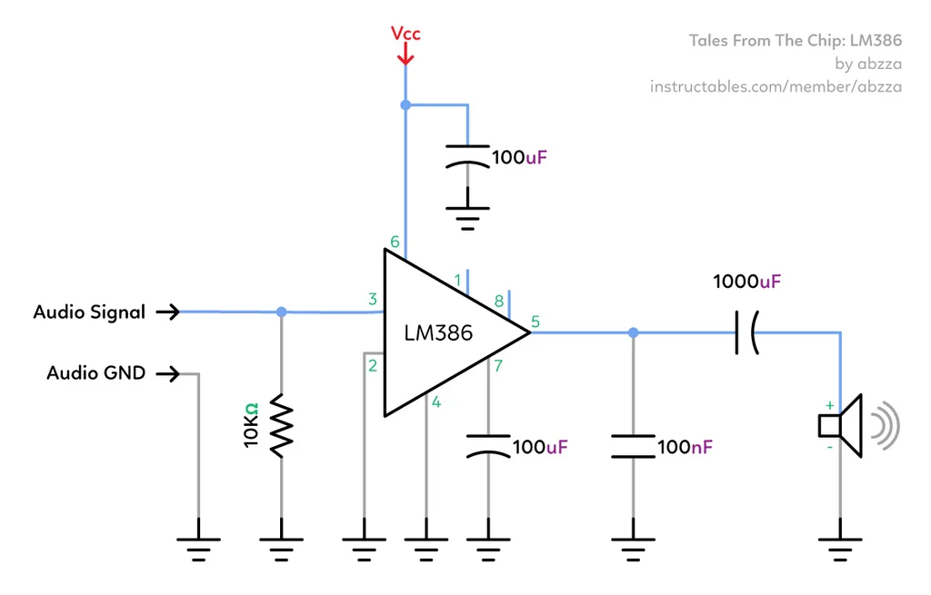
For instance, you’ll learn how to go from a circuit diagram like this one from this great LM386 amplifier tutorial:
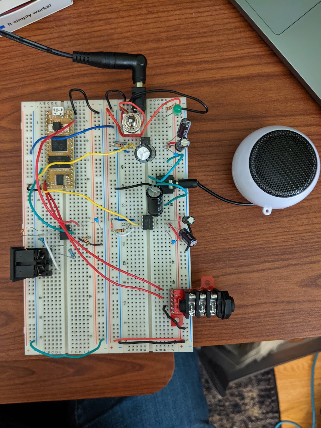
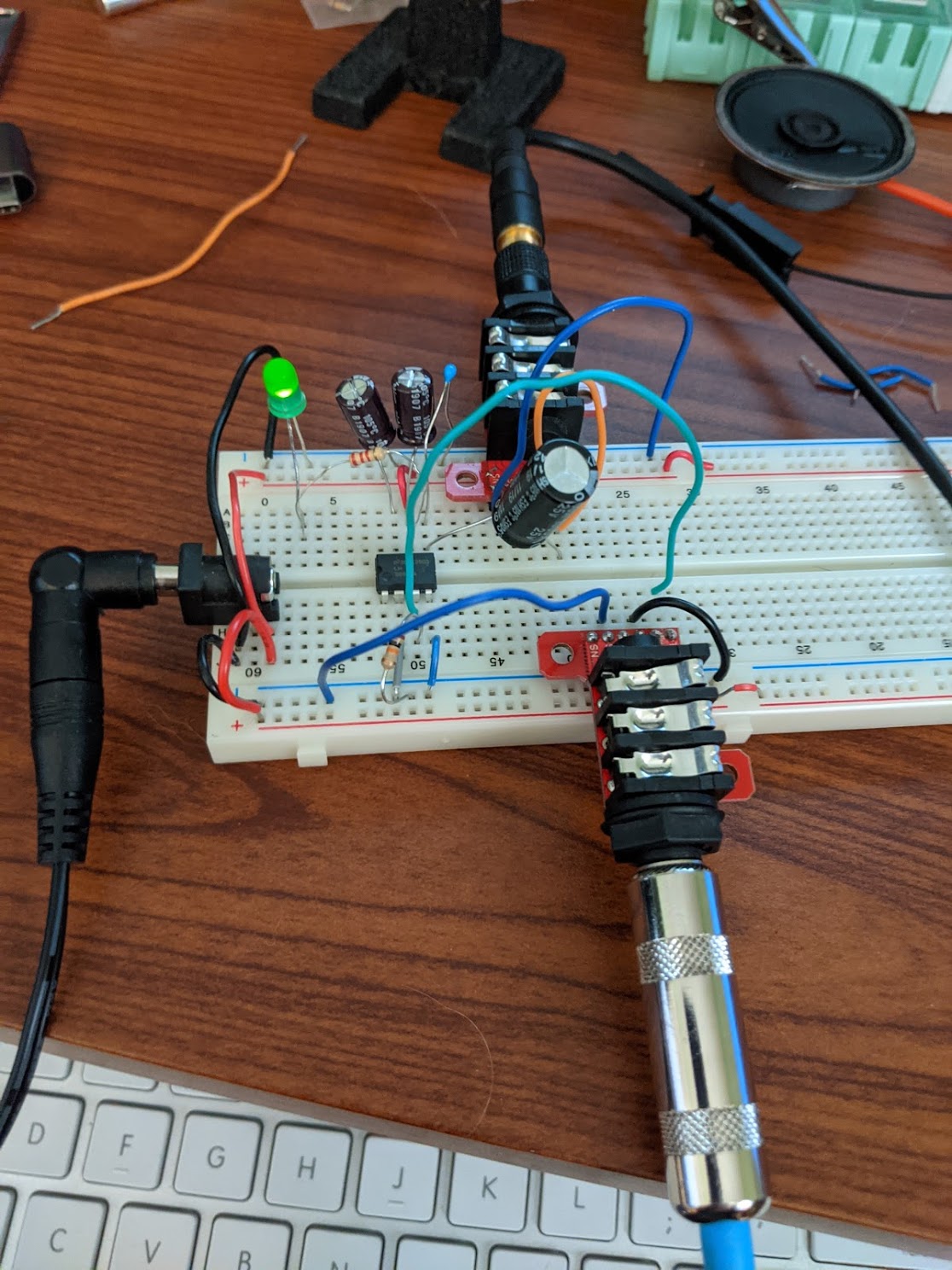
To the corresponding prototype implementation of this circuit, using a tool known as a solderless breadboard. These boards allow you to try out circuit design prototypes by plugging throughhole components into holes before committing to a design by soldering it together.
What is “bare metal”?
One thing to be aware of when diving into embedded development is that there are a number of subcategories under that umbrella that may bring unnecessary confusion during a Google search. The following articles will be discussing “bare metal” C++ development, but I’d like to briefly discuss a few of these other subcategories to give some context. They all share common elements, but differ enough that it is good to know (for instance) whether advice you find for one type will apply to your current efforts.
Bare metal development
“Bare metal” is sometimes a contested term, but I use it simply to mean development for a microcontroller with no operating system. When developing for a bare metal system, you usually have a library specific to the board (or family of boards) that you are developing for, which defines hardware registers that you read from or write to directly, rather than passing through an interface provided by an OS. You often are writing drivers yourself (or are using vendor provided ones, that you could modify if desired) and don’t need to go through an OS to perform the lowest level operations. Elecia White’s Making Embedded Systems is a great introduction to bare metal programming, with concepts that will also aid when getting into other types of embedded development.
While there are less guardrails in bare metal development, it also is a less distracting way to learn about embedded programming compared to the following approach.
Embedded Linux development
The other extreme for programming microcontrollers, opposite bare metal programming, is embedded Linux development. This entails building a custom Linux distribution that works with your target hardware that includes your application software. When starting from scratch, embedded Linux can be much more complicated than bare-metal, due to the complexity of rolling your own Linux distro (either manually, or more likely via a build system such as Yocto or Buildroot). There is also the potentially significant extra runtime overhead of running an OS on your target and development overhead of getting around the OS to perform low level operations.
However, embedded Linux can be a powerful way to develop and is the go-to approach for writing or porting cross platform software that can more easily be deployed to native platforms like macOS or Windows (or even native Linux). Sometimes the ability to leverage an OS outweighs the runtime cost, especially if your application requires you to reimplement many of the features that Linux would have offered anyway.
RTOS-based Development
Between the extremes of “bare metal” and “OS-based” embedded programming is programming using an RTOS (“ar-toss”), a Real-Time Operating System, the most common of which you’ll likely come across being FreeRTOS. These operating systems exist with a range of features, but their core feature is a real-time scheduler.
A bare metal application can integrate the features of an RTOS but still, for the most part, “feel” like a baremetal application, which is why I place it somewhere in the middle. For instance, you may write all your I2C or SPI drivers to communicate with peripherals, and then leverage FreeRTOS scheduler for the realtime functionality of your application.
FPGA Programming
The last type I’d like to mention is FPGA (field-programmable gate array) programming. This is a different beast than the types of development listed above, which focus on programming a microcontroller with a higher level programming language like C++ or Python.
When designing an FPGA, you use an HDL (hardware description language) to directly configure the digital logic gates on the device. FPGAs can be used to great effect in performance critical parts of a device. If interested, check out this Sparkfun tutorial.
Anatomy of a Bare Metal Synth
So with the above context in mind, the next few posts are going to look at a bare metal synth using the Electrosmith Daisy platform, on the STM32-based Daisy Seed. This platform offers, in addition to the STM32 vendor-provided libraries, a suite of music-geared drivers and DSP modules that make developing embedded music devices a lot more straightforward. I like it as a learning tool especially, since their libraries are transparent and make it simpler to tinker with what is happening under the hood.
Here’s what the synth sounds like:
Other similar platforms you may find for starting bare metal development are the Arduino and Teensy platforms. These are both more general purpose and will involve finding libraries and peripherals in order to create audio devices, whereas the Daisy is music-geared out of the box, with features like an on-board audio codec and USB MIDI support. However, Daisy still allows us to look at how usual bare metal techniques work, like pin multiplexing and gpios, communication protocols, etc, so it strikes a nice balance for these articles.
This is a signal flow diagram of the components we will go over.
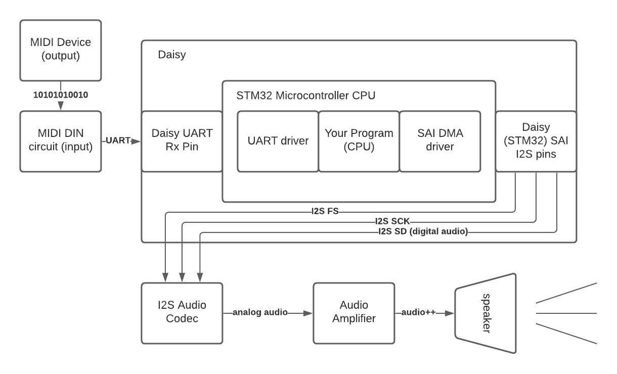
Specifically:
- MIDI data comes in from some generator or MIDI controller
- MIDI data goes through a MIDI isolator circuit
- Isolated MIDI is sent to the UART Rx pin on the Daisy
- The UART driver on the Daisy makes the MIDI data available to your application
- Your application interpets this MIDI and generates digital audio data in response
- That digital audio is sent to the STM32’s SAI (serial audio interface) as an I2S signal
- The SAI sends that I2S signal to an audio codec (D/A converter) to create analog audio
- That analog audio is optionally amplified before being sent to a speaker or line out
Up next: MIDI
This article served as an overview and introduction to where we are headed next. Check out the next one for info on the first part of the signal flow for our synth: the MIDI input.